Hub dynamo

A technology for in-wheel motor and magnetic flux collection, which is applied to synchronous machines, electromechanical devices, electrical components, etc., can solve the problems of weak support strength and magnetic flux saturation of the support part, achieve better performance, reduce magnetic saturation, and achieve smaller diameters Effect

Inactive Publication Date: 2006-08-30
MITSUBA CORP
View PDF2 Cites 18 Cited by
  • Summary
  • Abstract
  • Description
  • Claims
  • Application Information

AI Technical Summary

Problems solved by technology

Among them, only the magnetic flux collecting pieces are supported on the outer periphery of the iron core at both ends of the axle, so there are problems such as magnetic flux saturation in the supporting part and weak supporting strength.

Method used


Image

  • Hub dynamo
  • Hub dynamo
  • Hub dynamo

Examples


Embodiment Construction

[0045] Next, a first embodiment of the present invention will be described with reference to the drawings.

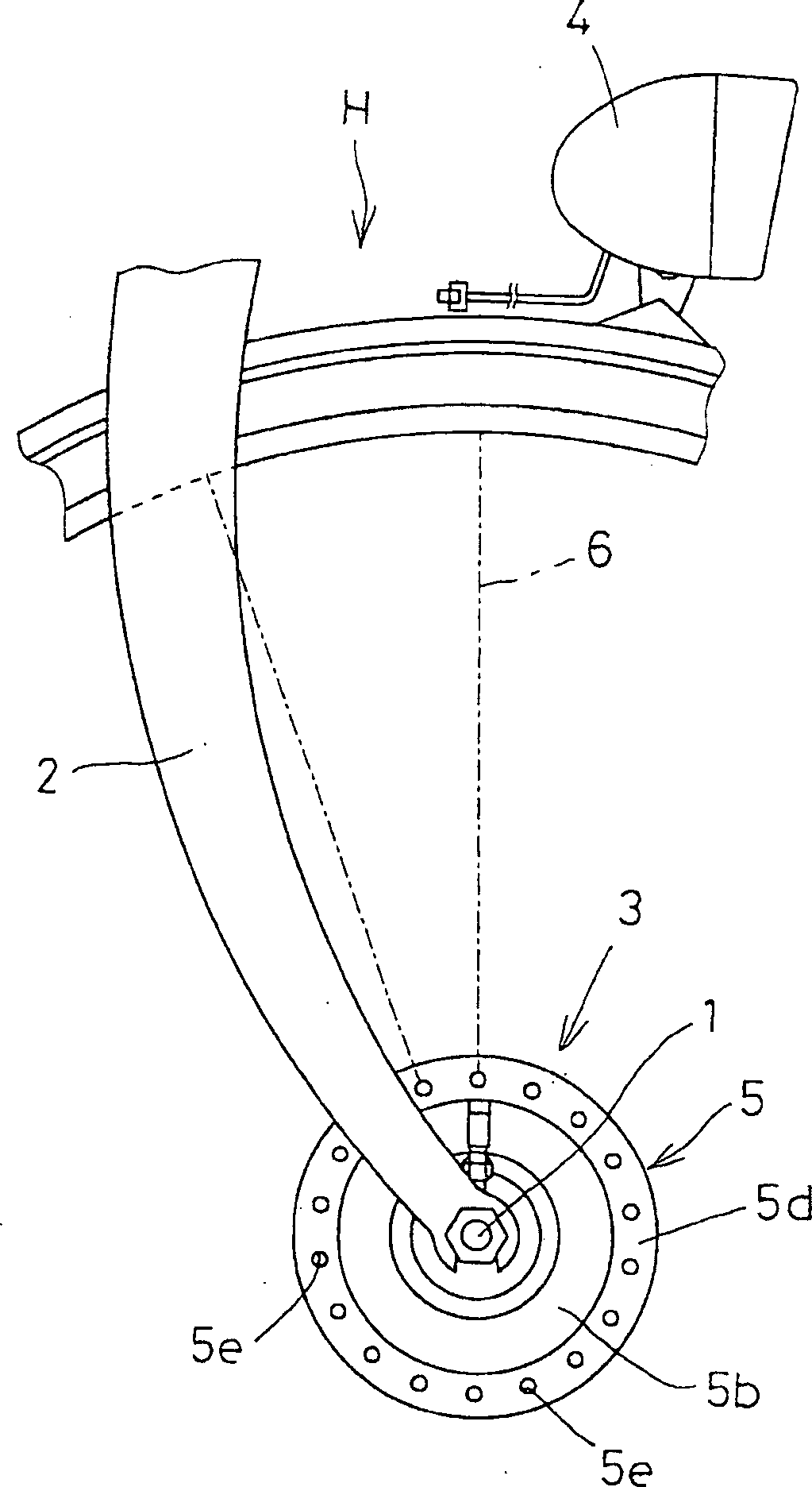
[0046] In the drawings, 1 is an axle constituting the rotation center of a front wheel (front wheel) H of a bicycle. The left and right ends of the axle 1 are supported by a pair of left and right front forks 2 constituting the vehicle body. The hub motor 3 implemented by the present invention is equipped with on the axle shaft 1.

[0047] In addition, 4 is a headlight connected so as to be lit by receiving electric power from the in-wheel motor 3 .

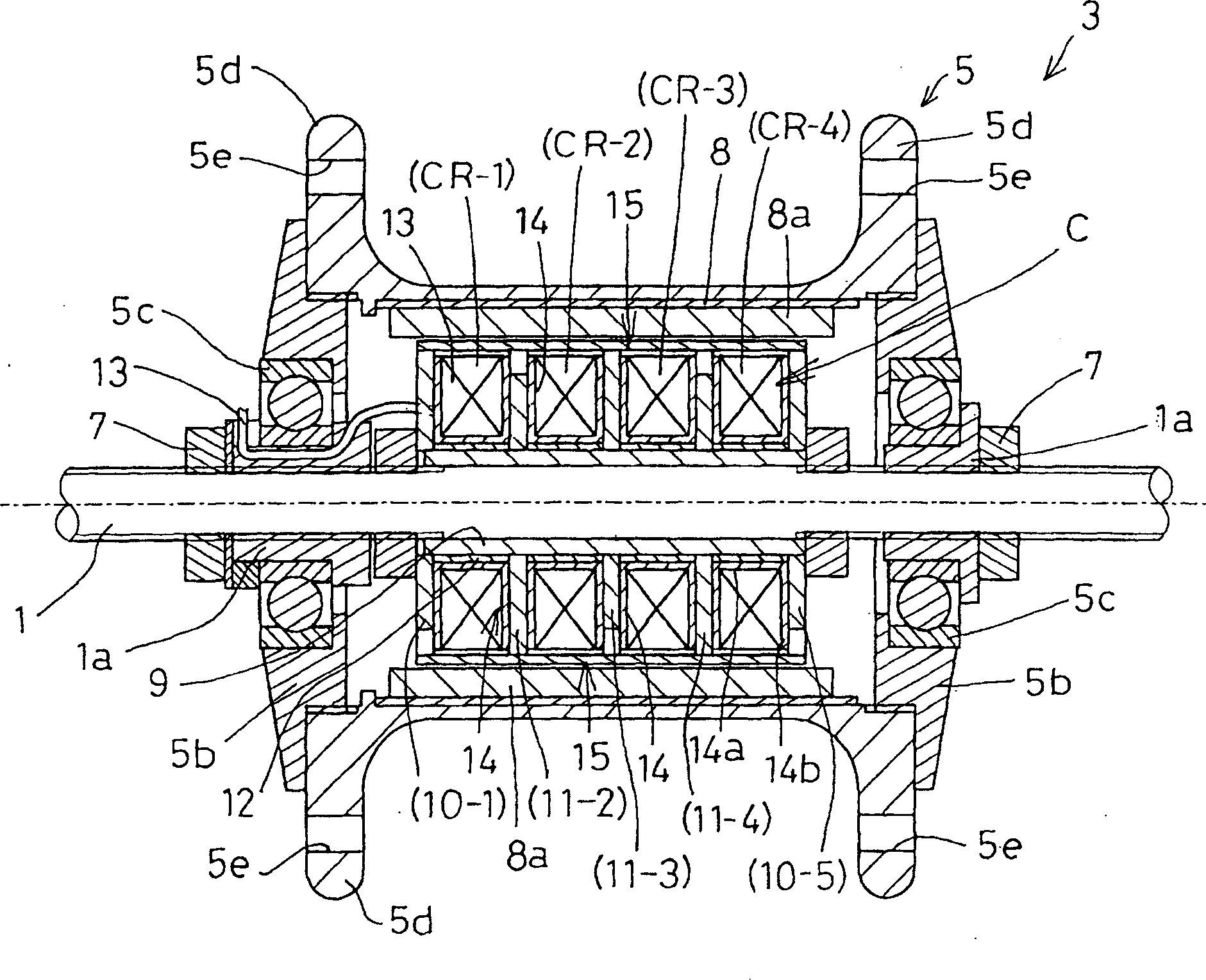
[0048] 5 is a casing (hub) constituting the in-wheel motor 3, and the casing 5 is integrally arranged by a cylindrical body portion 5a on which the axle 1 is fitted, and a cylindrical opening formed at both axial ends of the body portion 5a. A left and right pair of tailstocks 5b constitutes. The tailstock 5b is made of a ring-shaped plate, and is provided through a bearing 5c ​​provided on the outer periphery of a bush ...


PUM


Abstract

A hub dynamo is compacted into a small diameter size while ensuring the generation of a high voltage of electric power. A coil chamber CR formed between a pair of main iron cores 10 is partitioned in the axial direction by three sub iron cores 11 to form a first, second, third and fourth coil chambers (CR-1, 2, 3 and 4); on these coil chambers (CR-1, 2, 3 and 4), one coil wire 13 is wound in order in a state that the winding direction changes alternately; and magnetic flux collectors 15 connected with the outer circumference of the main / sub iron cores 10 and 11 include a first magnetic flux collector 15 connected with the first, third and fifth iron cores (10-1), (11-3) and (10-5) and a second pole piece 15 connected with the second and fourth iron cores (11-2), (11-4), which are disposed alternately.

Description

technical field [0001] The present invention relates to a hub motor mounted on a fork forming a bicycle frame. Background technique [0002] Usually, the structure of this kind of bicycle is that a generator is installed on the axle mounted on the fork that constitutes the frame, and the wheels that rotate as the bicycle travels generate electricity, and the headlights, etc. are turned on by the electric power obtained thereby. . In an in-wheel motor as such a generator, it is required to achieve a compact structure and to ensure high voltage without speed-up driving. For example, permanent magnets whose magnetic poles are alternately arranged in parallel in the circumferential direction are disposed on the inner circumference of the rotor (yoke) on the wheel side. The winding between) constitutes. Wherein, the iron core has a plurality of magnetic flux collection pieces (magnetic pole pieces) to obtain multi-polarization, and the coil is embedded in the iron core (for ex...

Claims


Application Information

Patent Timeline
Patent Type & Authority Applications(China)
IPC IPC(8): H02K21/22B62J6/12H02K1/14H02K7/18
CPCH02K21/227H02K1/145H02K7/1846
Inventor 丝井宪治南秀行白砂晃市依田健高草木龙一
Owner MITSUBA CORP
Why Eureka
Try Eureka