Tapping screw making method

A manufacturing method and technology of self-tapping screws, which are applied in the direction of elements with teeth, gear teeth, belts/chains/gears, etc. The effect of long mold life and reduced mold loss

Inactive Publication Date: 2006-09-06
陈河田
View PDF0 Cites 9 Cited by
  • Summary
  • Abstract
  • Description
  • Claims
  • Application Information

AI Technical Summary

Problems solved by technology

This molding method is as figure 1 , figure 2 Excessive extrusion pressure for in-mold forming on the punching die will also occur in the prior art, causing the shortcoming of rapid damage to the die

Method used


Image

  • Tapping screw making method
  • Tapping screw making method
  • Tapping screw making method

Examples


Embodiment Construction

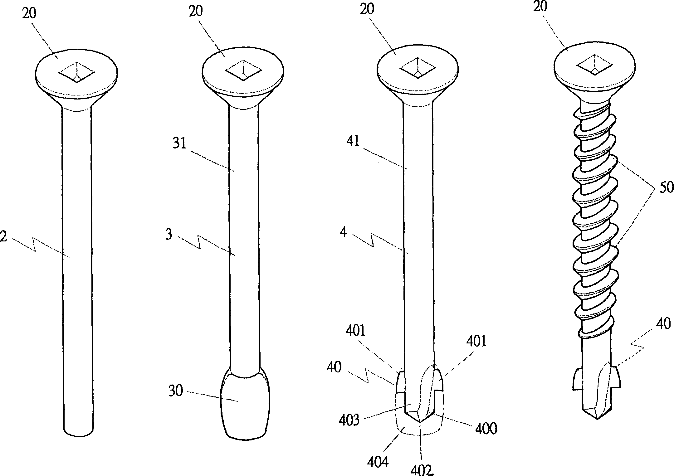
[0028] Such as image 3 , Figure 4 Shown, the present invention comprises the steps:

[0029] Preparing the primary blank: First, cut the metal raw material according to the required length to obtain a metal rod-shaped primary blank.

[0030] Cap forming: the primary blank is placed in the first forming mold, and the primary blank is punched with the cap 20 by using the first forming mold to produce the first blank 2 with the cap 20 .

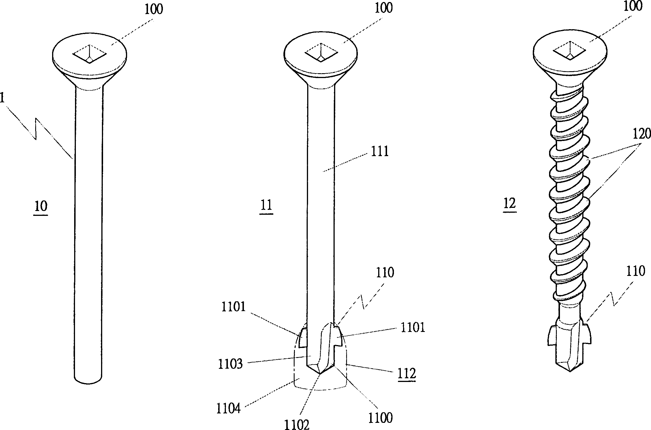
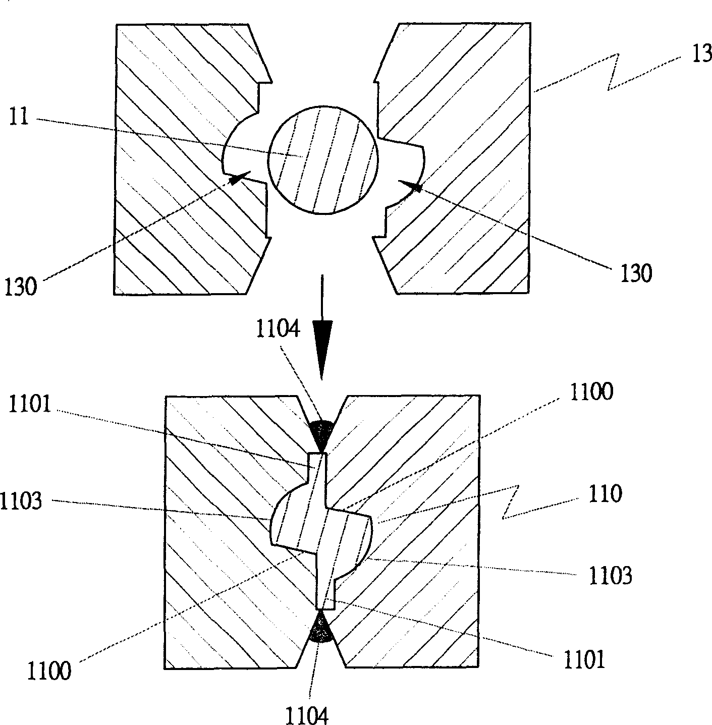
[0031] Tail molding: as Figure 4 , Fig. 5, shown in Fig. 6, the first blank material 2 is inserted in the second molding die 3A, utilizes the die groove 3A0 of the second molding die 3A to punch the other end of the first blank material 2 to form a The tail portion 30 of the diameter of the stem portion 31 is like the second stock 3 of the flat tail portion 30 , and the width of the flat tail portion 30 is greater than the diameter of the stem portion 31 . The second blank 3 in the tail forming step is only punched into the molding tail 3...


PUM


Abstract

The invention relates to a method for preparing self-taping screw which can reduce the mold consumption, increase the mold service life, and reduce the producing cost, which comprises following steps: initial blank preparation, cap molding, tail molding, cutting part molding, and screw molding. Wherein, the cap molding step is that arranging the initial blank into the first molding mold to punch the cap to attain the first blank with cap; the tail molding step is that: arranging the first blank into the second molding mould and using the second molding mould to punch another end of first blank to form the second blank with tail; the cutting part molding step is that: arranging the tail of second blank into the third molding mould to punch the tail to form the third blank with cutting part; and the screw molding step is that: via the thread rolling of forth molding mould on the rod of third blank, forming the screw rod with screw thread and removing the burr of cutting part.

Description

technical field [0001] The invention belongs to a method for manufacturing fasteners, in particular to a method for manufacturing self-tapping screws. Background technique [0002] Such as figure 1 , figure 2 As shown, the existing manufacturing method of self-tapping screw 1 comprises the following steps: [0003] For forming the cap, firstly, a metal rod-shaped primary blank made from a metal raw material is placed in a first forming mold, and the cap 100 is punched to produce the first blank 10 . [0004] Cutting forming, the first blank 10 is punched into a second blank 11 having a cutting portion 110 through a second forming die. [0005] Thread forming, the rod 111 of the second blank 11 passes through the thread rolling action of the third forming die to roll out the thread 120 to make a screw, and remove the burr 112 of the cutting part 110 at the same time, and then it can be made into a screw with self-tapping screw. Functional screw, that is, the finished sel...

Claims


Application Information

Patent Timeline
Patent Type & Authority Applications(China)
IPC IPC(8): B23P13/02B23F7/00B23F9/00B21D22/02
Inventor 陈河田
Owner 陈河田
Why Eureka
Try Eureka