Component mount method and component mount apparatus using the same

An installation method and component technology, applied in the direction of electrical components, electrical components, general control systems, etc., can solve the problem of time-consuming reading of barcodes, and achieve the effect of improving reliability

Inactive Publication Date: 2006-09-13
YAMAGATA CASIO CO LTD
View PDF1 Cites 34 Cited by
  • Summary
  • Abstract
  • Description
  • Claims
  • Application Information

AI Technical Summary

Problems solved by technology

[0041] In this way, the system using barcodes has the following problems: In any case of parts management, produc

Method used


Image

  • Component mount method and component mount apparatus using the same
  • Component mount method and component mount apparatus using the same
  • Component mount method and component mount apparatus using the same

Examples


Embodiment 1

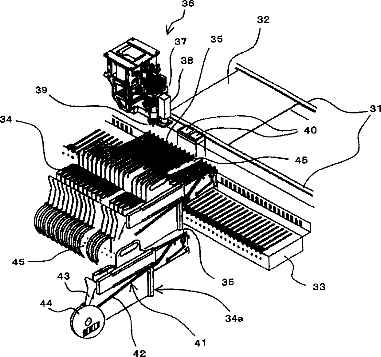
[0072] FIG. 1 is a diagram schematically showing the internal structure of a main part of a component mounting apparatus that executes component mounting processing using the component mounting method of the present invention that prevents component setting inconsistency at the time of component replacement. In addition, the general appearance of the component mounting apparatus of this example is the same as the component mounting apparatus 1 shown in FIG.11(a).

[0073] Shown in Fig. 1: 2 substrate guide rails 31; The substrate 32 that is sent in; Supply table 33; (Y direction) move left and right (X direction) to perform component mounting operations; 6 rotating mounting heads 37 are held on the operation head 36, lift up and down (Z direction), and rotate freely at 360 degrees; substrate identification cameras 38, Arranged near this mounting head 37, in order to carry out image recognition to the position marks etc. of the substrate 32, it is carried out photographing; Th...


PUM


Abstract

The part installing device can avoid the disconformity during part replacement for product altering regulation and in practical operation. During base plate unit production and when some part is used up, the first judgment of whether to be the chip part is performed, if yes, the common chip part replacing treatment is executed before re-producing base plate unit, and or else, the non-chip part replacing treatment is executed before the second judgment. In the second judgment, the image of the replaced part is obtained with the camera and the part shape characteristics are recognized for being identical with the pre-stored ones, and in case of disagreement, the warning report and part replacement is executed before returning to the image recognition. When the replaced part has the same shape characteristics, the third judgment for the identity in the characters on the surface of the part is executed before re-starting production if identical or executing the disagreeing treatment if not identical.

Description

technical field [0001] The present invention relates to a component mounting method and a component mounting device using the method for preventing component installation differences during production changeover and component replacement during actual operation. Background technique [0002] Conventionally, there is such an electronic component mounting device (hereinafter referred to simply as a component mounting device): the substrate supply device on the upstream side of the production line, the distributor, and the rotary kiln on the downstream side of the production line constitute the production line together, and are fed into the device itself. Electronic components (hereinafter referred to as components) are automatically mounted on printed circuit boards (hereinafter referred to as substrates) to produce substrate units. [0003] FIG. 11( a ) is an external perspective view showing an example of such a component mounting device in perspective. FIG. 11( b ) is a pe...

Claims


Application Information

Patent Timeline
IPC IPC(8): G05B19/402G06F12/00G06F17/00H05K13/04
Inventor 木村文昭
Owner YAMAGATA CASIO CO LTD
Why Eureka
Try Eureka