Power supply method of asynchronous machine

A power supply method and asynchronous motor technology, applied in the field of power electronics and power transmission, can solve the problems of increasing switching loss, stimulating audio noise, interfering with electronic equipment, etc., and achieve the effects of reduced switching noise, high torque and power

Inactive Publication Date: 2006-09-13
赵荣祥 +3
View PDF0 Cites 2 Cited by
  • Summary
  • Abstract
  • Description
  • Claims
  • Application Information

AI Technical Summary

Problems solved by technology

These methods result in higher electromagnetic interference (EMI) around the motor and increase switching losses due to higher device switching frequency
This kind of EMI not only increases the electrical stress of the switching device and interferes with the surrounding electronic equipment, but also produces audio noise that irritates the human ear if the switching frequency is within the audio frequency range.

Method used


Image

  • Power supply method of asynchronous machine
  • Power supply method of asynchronous machine
  • Power supply method of asynchronous machine

Examples


Embodiment Construction

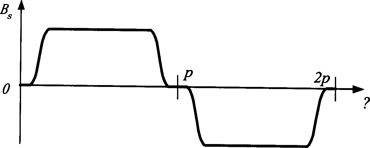
[0017] The technical solution of the present invention considers that the more the number of phases, the closer the magnetic field is to a square wave. Each pole of the existing three-phase asynchronous motor has three phase belts, and each phase has two or more than two slots. Each pole of the asynchronous motor of the present invention adopts m phase belts (m≥3, m may not be a multiple of 3), and each phase belt has only one or a few slots, so that the motor becomes an m-phase (m≥3) motor ;

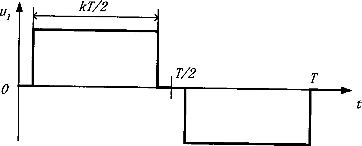
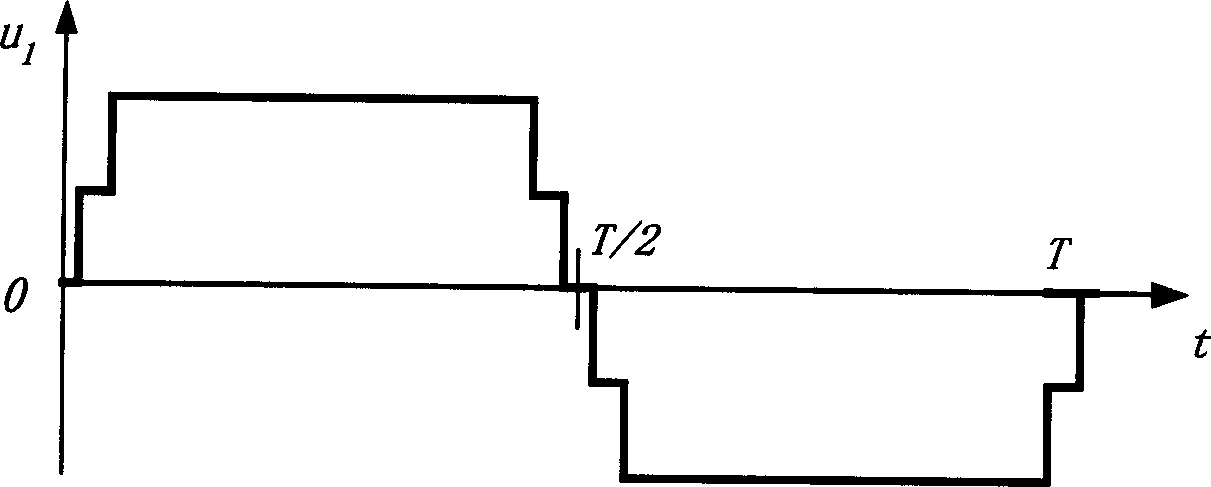
[0018] The voltage applied to the motor in the prior art is generally a sine wave voltage, which is changed to an m-phase (m≥3) quasi-square wave voltage in the present invention. The quasi-square wave voltage mainly refers to the following three voltage waveforms, which are explained with reference to the attached drawings:

[0019] (1) is a short distance square wave voltage, as attached figure 1 shown. where the ordinate u 1 Represents the instantaneous value of a certain phase ...


PUM


Abstract

This invention puts forward a supply method for asynchronous motors, which enables inside of a multi-phase asynchronous motor to generate a square-wave magnetic field, in which, the phase of the motor is greater than or equal to 3, the voltage added to each phase winding is the quasi-square-wave voltage and the field distribution is the quasi-square-wave field in saddle or bread shape so as to increase output, save raw materials and increase efficiency.

Description

technical field [0001] The invention belongs to an asynchronous motor and relates to power electronics and power transmission technology. Background technique [0002] At present, asynchronous motors are basically three-phase or single-phase motors, and their internal air-gap magnetic fields are distributed as sine waves or quasi-sine waves. This design is based on the fact that the existing conventional power supplies are all three-phase sine waves. [0003] In order to achieve speed regulation, frequency conversion and voltage conversion power supply are required. To achieve this goal, the current popular solution is to use power electronic variable voltage variable frequency speed control device, but the motor itself or the application method has not changed. In order to convert the power frequency of the power grid into a frequency-adjustable power supply, the conventional method is to first rectify the AC to DC, and then generate a sinusoidal AC of the required freque...

Claims


Application Information

Patent Timeline
Patent Type & Authority Applications(China)
IPC IPC(8): H02P27/00
Inventor 赵荣祥吕征宇赵光宙汪槱生
Owner 赵荣祥
Why Eureka
Try Eureka