Multiple carrier-frequency digital frequency source

A technology of multiple carrier frequencies and frequency sources, applied in the field of electronic information, can solve the problems of difficult to use frequency sources, narrow target area, etc., achieve the effect of low spurious free dynamic range, maintain consistency, and reduce development time

Inactive Publication Date: 2006-09-13
XIDIAN UNIV
View PDF0 Cites 35 Cited by
  • Summary
  • Abstract
  • Description
  • Claims
  • Application Information

AI Technical Summary

Problems solved by technology

This method has good scalability and is suitable for the application of si...

Method used


Image

  • Multiple carrier-frequency digital frequency source
  • Multiple carrier-frequency digital frequency source
  • Multiple carrier-frequency digital frequency source

Examples


Embodiment Construction

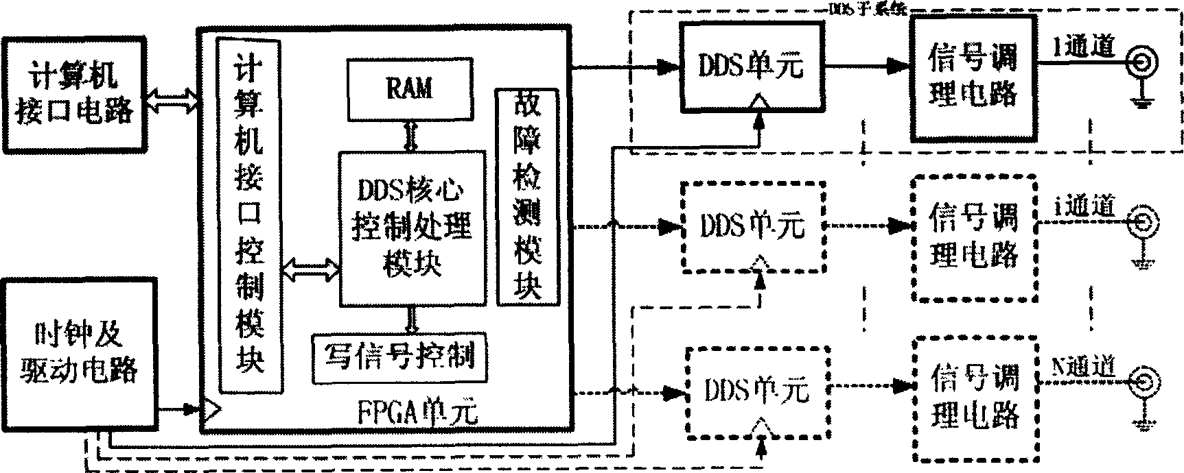
[0040] refer to figure 1 , the present invention is made up of FPGA, a plurality of DDS subsystems, clock and drive circuit, computer interface circuit, and each DDS subsystem forms the output of a channel, and the structure of each part is as follows:

[0041] 1.FPGA unit

[0042] The FPGA or ASIC unit can be realized by FPGA programming or converted into an ASIC chip, and the unit includes logic parts such as DDS core control module, fault detection module, computer interface control module, etc. Among them, the DDS core control module generates timing control signals for the DDS subsystem, that is, obtains various parameters of the system from the computer interface module, and controls the parameters of the output waveform of the DDS subsystem to meet the system requirements. The timing of the output waveform is based on It depends on the DDS chip selected by the system. The fault detection module is to prompt the user when the system fails, that is, to analyze the signa...


PUM


Abstract

This invention discloses a multi-carrier frequency digital frequency source including a computer interface circuit, a clock and drive circuit, a field programmable gate array FPGA unit, a direct digital synthesizing DDS sub-system, in which, said clock and drive circuit provides clock signals with strong driving ability to FPGA and DDS units in the system, said FPGA unit controls multiple same DDS sub-systems, each of which forms an independent channel output to generate different signal kinds, signals of different modulations, different frequencies and phases according to the time sequence sent by the FPGA unit and generates echo analog signals by simulating actual signals, especially the LFMICW signals.

Description

technical field [0001] The invention belongs to the technical field of electronic information and relates to digital frequency synthesis, in particular to a multi-carrier frequency digital frequency source, which can be used in the occasions where multiple synchronous intermediate frequency signal sources are required to be provided simultaneously in the fields of radar and communication. Background technique [0002] For the design of digital frequency source, the following methods are usually adopted: [0003] 1. Design of low-noise and high-resolution direct digital frequency synthesizer, such as "Wideband Radar Signal Generation Technology, edited by Fei Yuanchun, Beijing, National Defense Industry Press, 2002.1". This method is composed of numerical control oscillator, level converter, digital-to-analog D / A converter, low-pass filter and single-chip control circuit, etc., which can achieve good spectrum performance. However, this method has too many separated component...

Claims


Application Information

Patent Timeline
IPC IPC(8): H03L7/00H03L7/16
Inventor 陈伯孝李锋林张守宏
Owner XIDIAN UNIV
Why Eureka
Try Eureka