Flowing water hydraulic generator

A technology of hydroelectric generators and generators, which is applied in the fields of hydroelectric power generation, engine components, machines/engines, etc. It can solve the problems of indistinguishable profit and loss, ecological environment damage, etc., and achieve the effect of low cost and alleviating the excessive power gap

Inactive Publication Date: 2006-09-20
郭世光
View PDF0 Cites 10 Cited by
  • Summary
  • Abstract
  • Description
  • Claims
  • Application Information

AI Technical Summary

Problems solved by technology

Closure and dam construction consumes a lot of manpower and material resources. After completion and production, the ecological environment is often severely damaged, so it is still difficult to distinguish between profits and losses, and both advantages and disadvantages coexist.

Method used


Image

  • Flowing water hydraulic generator
  • Flowing water hydraulic generator

Examples


Embodiment Construction

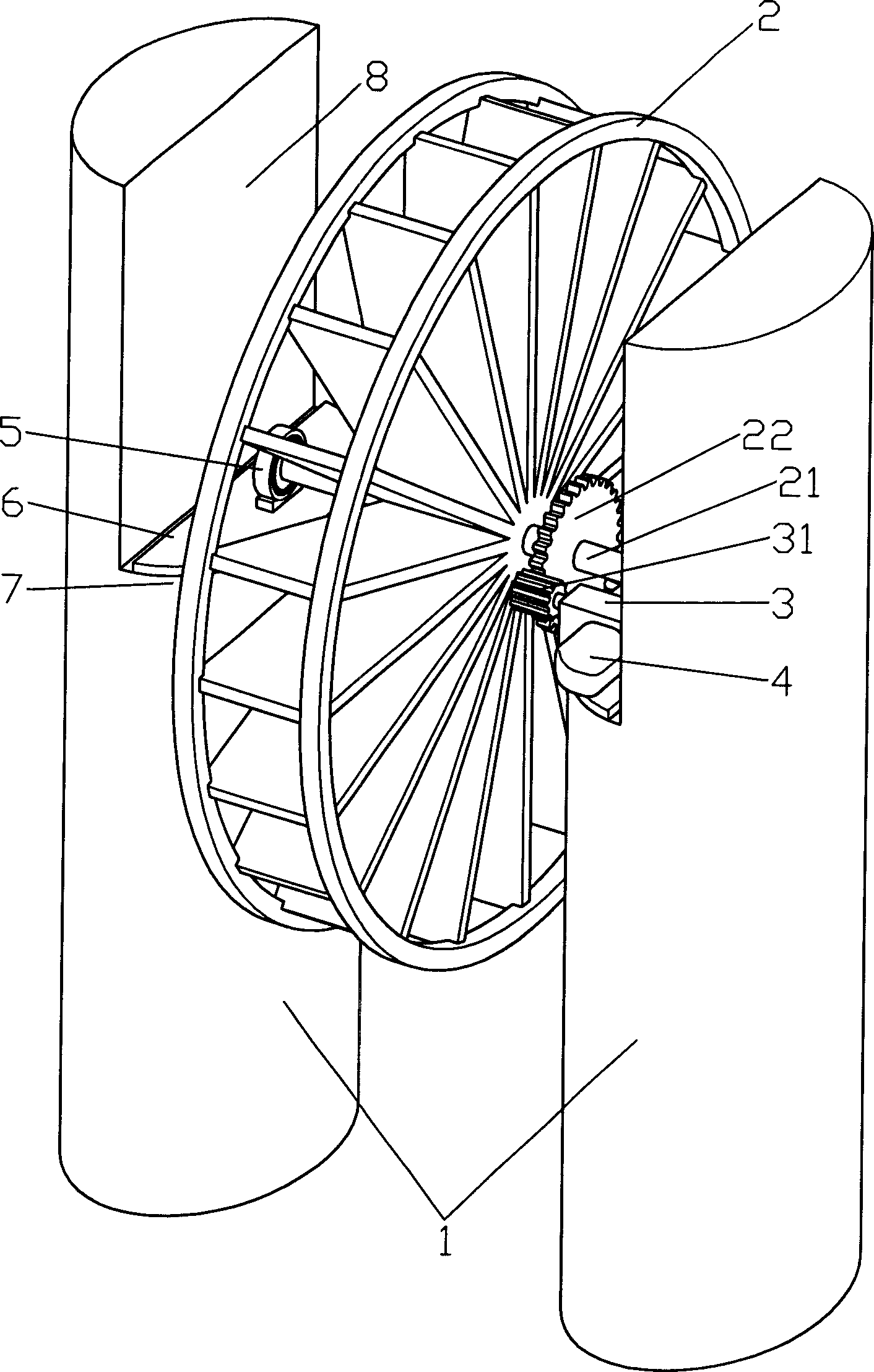
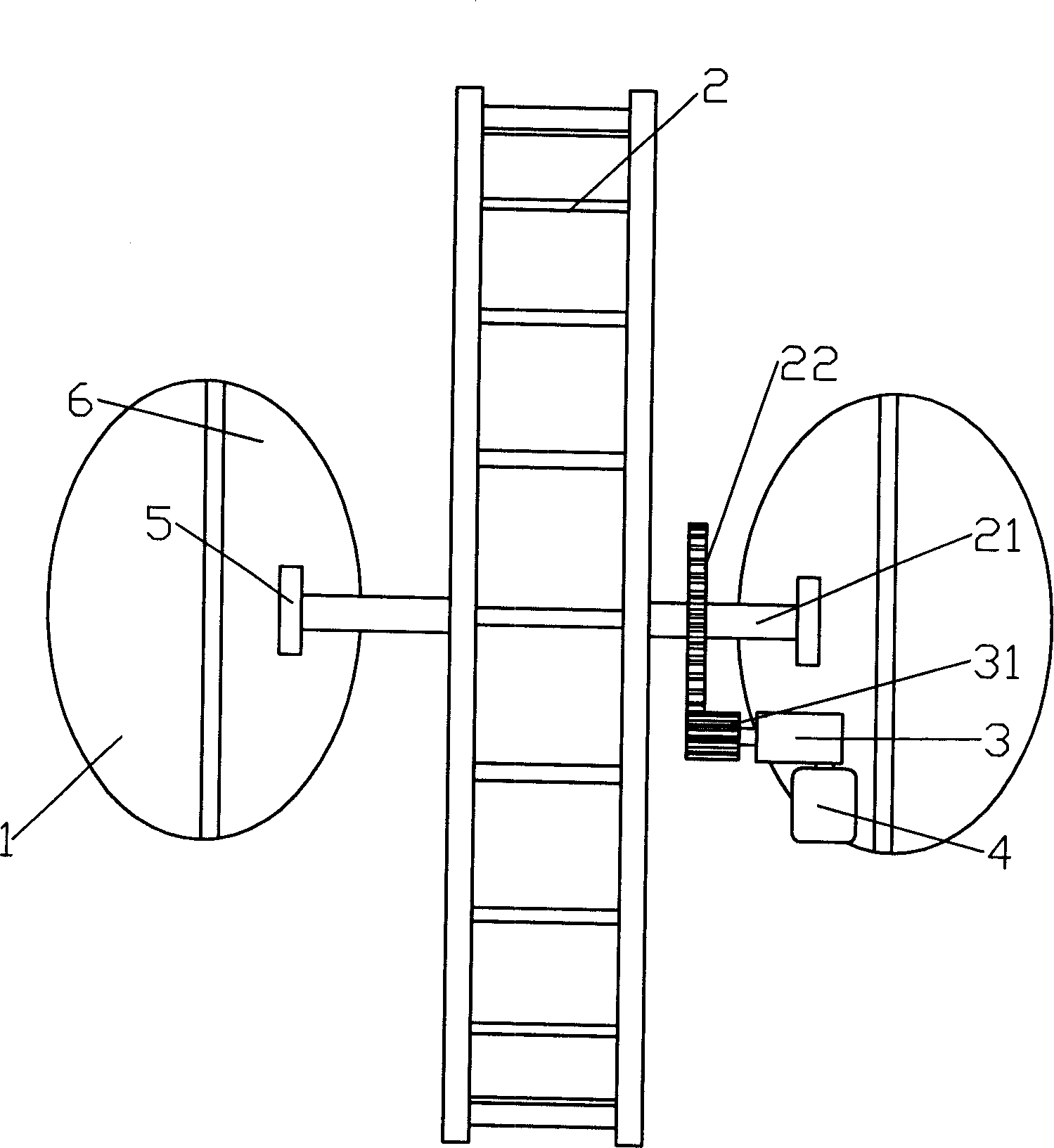
[0021] Such as figure 1 As shown, a schematic perspective view of a preferred embodiment of a flowing water hydraulic generator, including a water wheel 2, a generator 4, and it also includes two columns 1, a gearbox 3, and a lifting plate 6. Column 1 is built in running water, higher than the height of the highest water surface in the flood season of running water, the distance between the two columns is appropriate, and the column is a cement column with an elliptical cross section. The column 1 is fixed at the bottom of the running water, and the inner side opposite to the upper part of the column 1 is sunken downward to form a platform 7 , and the top of the column forms a boss 8 .

[0022] The water wheel 2 is a vertical water wheel with blades, the wheel shaft 21 is horizontal, and the transmission wheel 22 is fixed on the wheel shaft 21. 6 on the lifting platform. In practical application, the height difference between the wheel shaft 31 of the water wheel and the wat...


PUM


Abstract

The present invention relates to a water-flowing hydraulic power generator. It includes a water wheel and a power generator. Besides, it also includes two vertical columns constructed on the water bottom, gearbox and two lifting plates. Said two vertical columns are constructed in the water and fixed on the flowing water bottom portion, their heights are higher than water level of the following water; the water wheel is a vertical one, the wheel axle of said water wheel is horizontal, on the wheel axle a driving wheel also is fixed, two ends of said wheel axle are mounted on the bearing seats, and said two bearing seats are respectively fixedly mounted on two lifting plates, the lower portion of said water wheel is positioned under the water level; the gear of the gearbox is meshed with the driving wheel on the wheel axle of water wheel and main shaft of power generator, the gearbox and the power generator are also fixed on the lifting plates respectively. Said invention is characterized by changing the energy of motion of flowing water into electric energy by means of mechanical transmission.

Description

technical field [0001] The invention relates to a hydraulic generator, in particular to a directional watershed hydraulic generator. Background technique [0002] At present, the existing known hydroelectric power generation in the world requires a reservoir to store water, and requires a certain height of water flow drop, so as to generate power to drive the water turbine to achieve the effect of driving the generator to generate electric energy. In order to solve the problem of water storage and increase the water level drop, usually before the construction of this type of hydroelectric power station, a lot of assessment, survey, design and demonstration must be done in advance. Closure and dam construction consumes a lot of manpower and material resources. After the completion and production, the ecological environment is often severely damaged, so it is still difficult to distinguish between profits and losses, and both advantages and disadvantages coexist. Contents of...

Claims


Application Information

Patent Timeline
IPC IPC(8): F03B13/00F03B7/00
CPCY02E10/223Y02E10/20
Inventor 郭世光
Owner 郭世光
Why Eureka
Try Eureka