Thermal expansion valve having diversion function

A thermal expansion valve and function technology, applied in the field of thermal expansion valve, can solve the problems of uneven distribution of working medium by a distributor, easy to generate vibration and noise, and adverse air conditioning system operation, etc., and achieves small flow resistance, reduced vibration, practical strong effect

Inactive Publication Date: 2006-09-20
ZHEJIANG SANHUA CLIMATE & APPLIANCE CONTROLS GRP CO LTD
View PDF0 Cites 8 Cited by
  • Summary
  • Abstract
  • Description
  • Claims
  • Application Information

AI Technical Summary

Problems solved by technology

In the above-mentioned known expansion valve, the refrigerant flows through the valve port and then throttles and expands and flows to the outlet, resulting in chaotic flow of the fluid medium at the outlet of the expansion valve and uneven distribution of the flow field, which in turn causes vibration, noise, flashing gas and other defects of the expansion valve. The possibility of the phenomenon increases, especially when the expansion valve or the system has a distributor element, the uneven flow field causes the distributor to distribute the working medium unevenly, which is not conducive to the operation of the entire air conditioning system
In addition, the adjustment spring G3 is set on the passage between the high-pressure port G11 and the low-pressure port G12 of the valve body. When the cold medium flows through the valve port G13, it is hindered by the spring G3 and the flow resistance increases, which is prone to vibration and noise; To ensure that the spring can be effectively supported on the valve core, an adjustment component (such as an adjustment nut) must be provided at the lower end, which makes the structure of the expansion valve complex

Method used


Image

  • Thermal expansion valve having diversion function
  • Thermal expansion valve having diversion function
  • Thermal expansion valve having diversion function

Examples


Embodiment Construction

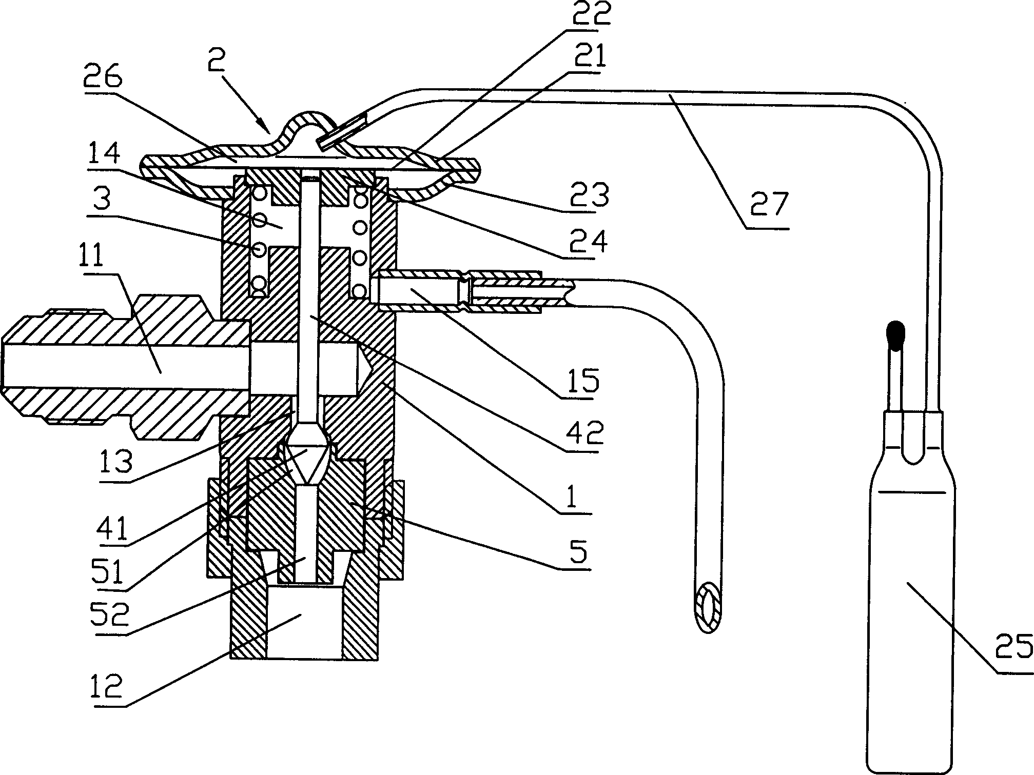
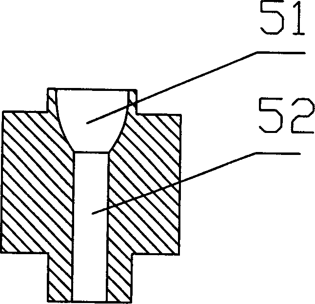
[0022] Such as figure 1 The thermal expansion valve shown includes a valve body 1, an air box head part 2, a valve core part and an adjustment spring 3. The valve body 1 has an inlet 11, an outlet 12 and a valve port 13 connecting the inlet and the outlet, and its upper end Open the accommodation cavity 14 for setting the adjustment spring, connect the external balance connecting pipe 15 from the accommodation cavity, and fix a flow guide element 5 at the lower end of the valve port 13, and open a flow guide channel connecting the valve port and the outlet on the flow guide element , a section of the diversion channel close to the valve port is an arc-shaped expansion part 51, and a section away from the valve port is an equal-diameter hole 52; And the temperature-sensing package 25, the air box seat 23 is fixed on the upper end of the valve body 1, the air box cover 21 and the diaphragm 22 form a sealed cavity 26, the temperature-sensing package 25 communicates with the seale...


PUM


Abstract

The present invention relates to a thermal expansion valve with the function of guiding flow. It is characterized by that in the end portion of valve port faced with outlet a flow-guiding channel is set, after having been passed through valve port and flow-guiding element the refrigerant is expanded, in the flow-guiding channel the refrigerant is flowed through curved expansion portion (streamlined portion) firstly so as to make working medium flow field be stable and uniform, then the refrigerant is passed through isometric hole portion, mixed and flow-guided to outlet so as to make the working medium in the outlet of expansion valve be stable and uniform. In particular, when the outlet of expansion valve is connected with distributor element, the distributor can be used for uniformly distributing expanded refrigerant medium, so that it can reduce vibration and noise, and can raise control performance of valve.

Description

【Technical field】 [0001] The invention relates to a thermal expansion valve structure for throttling and expanding a fluid medium, in particular to a thermal expansion valve with a diversion function. 【Background technique】 [0002] A thermostatic expansion valve, which controls the flow of fluid through the valve in response to a heat-induced fluid pressure signal, is particularly useful in refrigeration or air conditioning systems for controlling the flow of refrigerant into an evaporator. refer to figure 1 , the high-temperature and high-pressure gaseous refrigerant compressed in the compressor Y flows into the condenser L, is cooled into a high-pressure liquid refrigerant, enters the expansion valve P for throttling and pressure reduction, and then enters the evaporator Z through the outlet of the expansion valve to absorb heat and evaporate Then it is sucked into the compressor to complete a cycle. [0003] Known thermal expansion valve (see Figure 4 ) includes a va...

Claims


Application Information

Patent Timeline
Patent Type & Authority Applications(China)
IPC IPC(8): F16K1/00F16K1/32
Inventor 刘浪祝颖安吕灵秋吕刚明郑正松
Owner ZHEJIANG SANHUA CLIMATE & APPLIANCE CONTROLS GRP CO LTD
Why Eureka
Try Eureka