Supercharge Your Innovation With Domain-Expert AI Agents!

Method of mfg. optical component

A manufacturing method and technology of optical components, applied in the fields of optics, photographic plate-making process of patterned surface, optical mechanical equipment, etc., can solve problems such as uneven distribution of light energy and difficulty in correct positioning

Inactive Publication Date: 2006-09-20
FUJINON SANO
View PDF1 Cites 0 Cited by
  • Summary
  • Abstract
  • Description
  • Claims
  • Application Information

AI Technical Summary

Problems solved by technology

When a film is formed on one side of the elongated triangular prism with the end faces held in this way, there is a problem that it is difficult to position correctly because the area for holding is very small relative to the entire shape.
Especially when forming a reflective film having a slit, if the position of the slit is misaligned along the short axis direction, for example, in the case of an APC photodetector, there is a problem that the measured light energy distribution is not uniform, and accurate measurement cannot be performed. Light energy measurement

Method used


Image

  • Method of mfg. optical component
  • Method of mfg. optical component
  • Method of mfg. optical component

Examples


Embodiment Construction

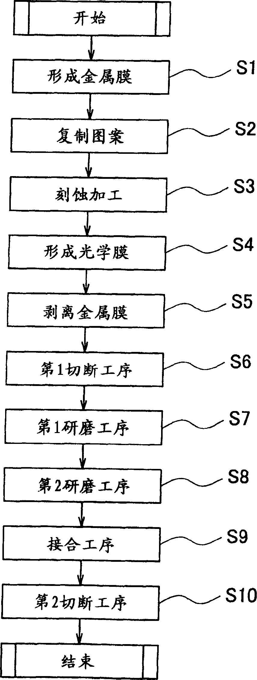
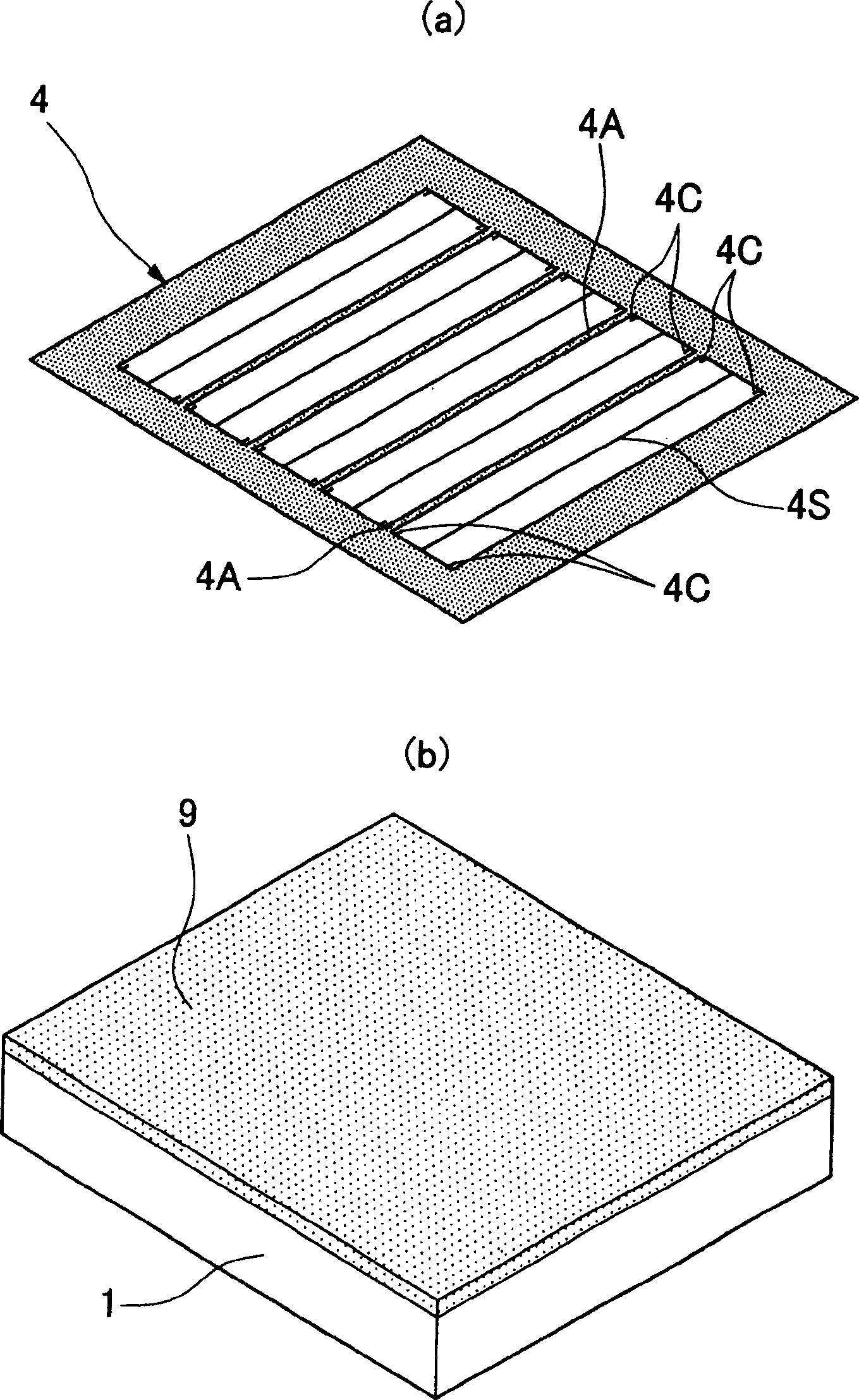
[0022] The following is based on figure 1 The flow chart of the figure illustrates an embodiment of the present invention. First, a large transparent substrate 1 such as a flat glass plate is prepared, and the metal film 9 is uniformly formed thereon (step S1). Here, although a square plate is used as the shape of the transparent substrate 1 for description in this embodiment, the present invention is not limited thereto, and the transparent substrate 1 may be in the shape of a circular plate. In addition, at this time, the surface of the large transparent substrate 1 on which the metal film 9 is formed is previously polished.

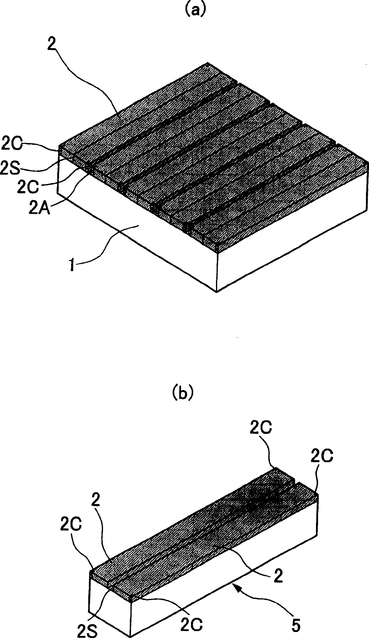
[0023] Then, like figure 2 As shown in (b), the flat plate-shaped large transparent substrate 1 formed with the metal film 9 is kept in a stable state, and a photosensitive agent such as a photoresist is coated on the surface, and used figure 2 The mask member 4 shown in (a) forms an exposure pattern by exposing the punched part of the mask membe...


PUM


Abstract

The invention could avoid location aberration of the micro transmission section in reflective coating formed on prism. The mask component forms a reflective coating on flat clarity base board and cuts the base board to gain base board block. Grinding the surface that has not formed reflective coating to the location of scale 2C, and combining the first prism structure sheet and the second prism structure sheet, final ortho-quadrangular prism would be formed.

Description

technical field [0001] The present invention relates to a method of manufacturing an optical element, and more particularly to a method of manufacturing an optical element that transmits only a part of incident light. Background technique [0002] An optical element in which a film having predetermined optical characteristics is formed on a transparent substrate such as a glass substrate can be used in various optical devices. Such an optical element includes an element that transmits or reflects light of a certain wavelength or more, an element that transmits or reflects light according to a polarized light component, or an element that reflects all incident light. There is also an element that transmits only part of the incident light and reflects all the other incident light. [0003] Wherein, as an optical element that allows a part of incident light to pass through an optical element used in a sensor device such as an optical disc, for example, there is a part that all...

Claims


Application Information

Patent Timeline
Patent Type & Authority Applications(China)
IPC IPC(8): G02B5/04G03F7/20G03F7/24
Inventor 横山岩关口隆史
Owner FUJINON SANO
Features
  • R&D
  • Intellectual Property
  • Life Sciences
  • Materials
  • Tech Scout
  • Unparalleled Data Quality
  • Higher Quality Content
  • 60% Fewer Hallucinations
Learn More