A fixation method for underground gas storage well bore

A fixing method and a gas storage well technology, applied in the container discharge method, container filling method, gas/liquid distribution and storage, etc., can solve the problems of difficult construction, inability to fix, wellbore rushing out of the ground, etc., to improve safety Performance and mission, simple fixing process, not easy to loose effect

Inactive Publication Date: 2010-09-01
自贡力源科技有限公司
View PDF4 Cites 6 Cited by
  • Summary
  • Abstract
  • Description
  • Claims
  • Application Information

AI Technical Summary

Problems solved by technology

However, due to the limitation of cementing quality, many gas storage wells are often scrapped before reaching the service life, and even wellbore stringing accidents occur
The traditional cementing method, one is to pour cement slurry between the wellbore and the well wall from top to bottom to fix it with the well wall. The gap between them is generally less than 3.0cm, and the cement slurry is difficult to reach the position below 10m, and the groundwater, drilling fluid and air between the wellbore and the well wall cannot be discharged; Underground Gas Storage Well Shaft Fixing Method" patent technology, sink a hose from one side of the wellbore, and grout from the bottom of the well; although this method overcomes the grouting from top to bottom, shallow depth, groundwater, drilling fluid and air Disadvantages that cannot be discharged, and the middle and lower parts of the wellbore cannot be fixed
However, the basic wells opened by geological drilling have poor verticality and uneven well walls, and the wellbore is rigid, so the grouting hose is easily crushed, so that the cement slurry cannot be poured down. The closed bottom is held up by the cylinder of the ball head, the construction is difficult, and the cement slurry is also difficult to pour from the bottom up to the ground, which affects the fixing effect
In addition, both of the above two traditional filling methods have a considerable part of the cylinder that cannot be covered by cement slurry, and the exposed pipe is also vulnerable to corrosion, which poses a safety hazard
Therefore, the above-mentioned background technology has the disadvantages of poor manufacturability and reliability of pouring cement slurry, and the wellbore is prone to up and down movement and rotation during use, especially when the ambient temperature changes greatly. Affect the normal use and service life, and pose a threat to the safety of equipment and staff

Method used


Image

  • A fixation method for underground gas storage well bore
  • A fixation method for underground gas storage well bore

Examples


Embodiment Construction

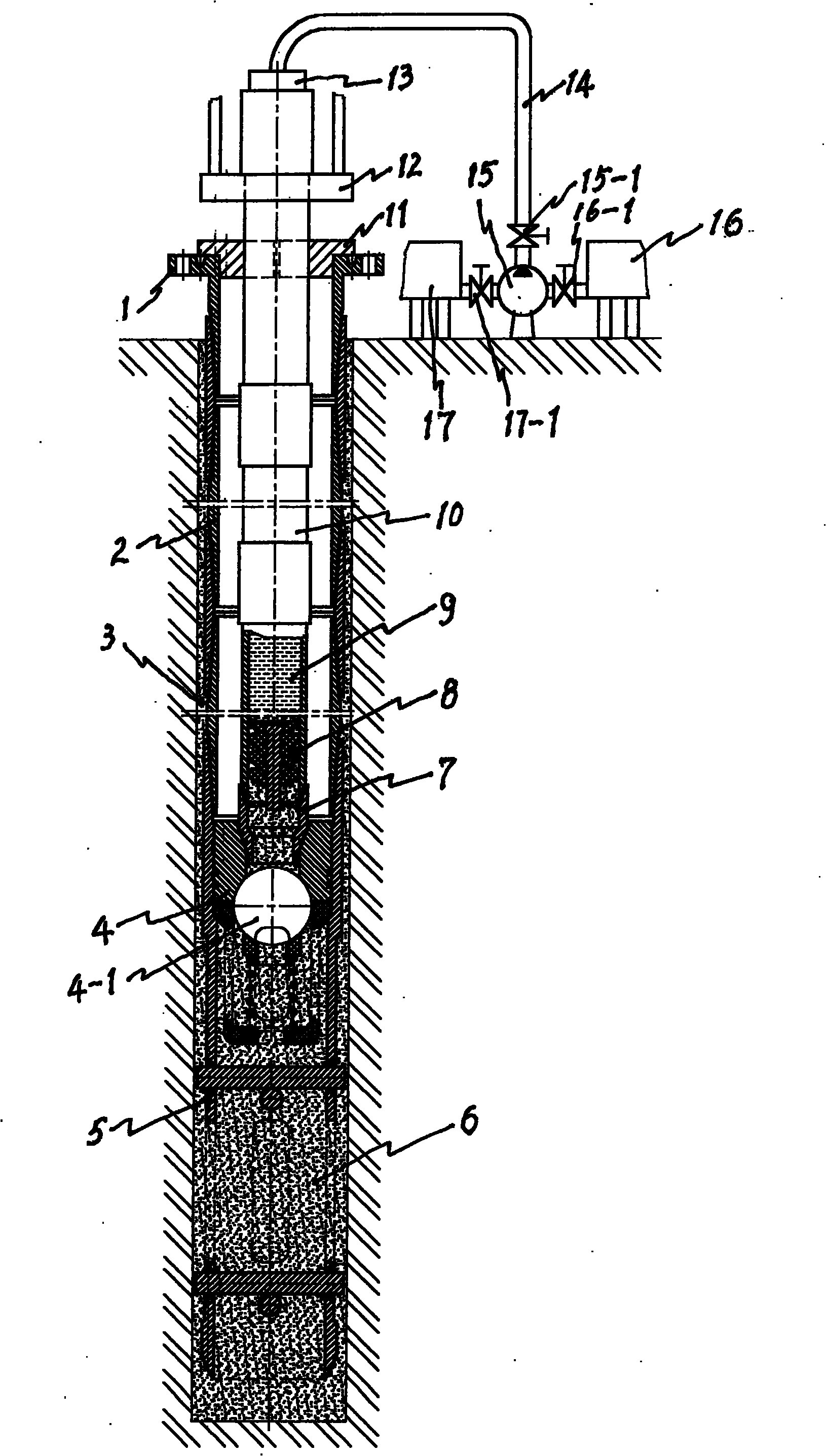
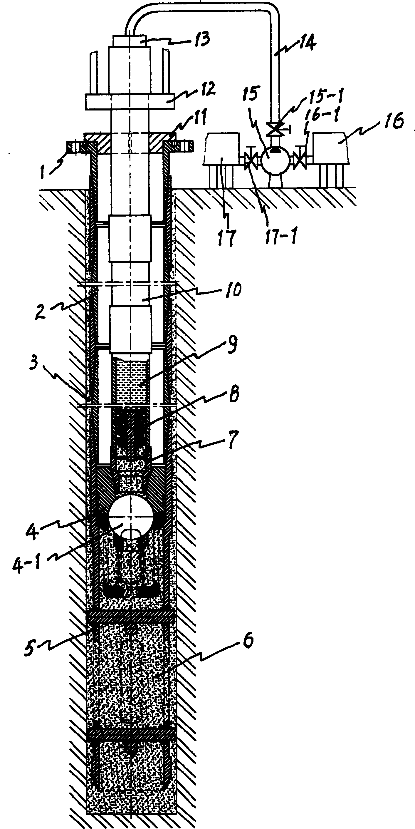
[0012] Take the fixing of a wellbore with an outer diameter of 7 inches and an effective gas storage length of 125m as an example:

[0013] A. Going down the wellbore: First, use the 7-inch conduit back pressure valve for oil and gas field drilling as the one-way valve 4, which is fastened to the bottom end of the wellbore 2 through the taper thread, and the lower end of the valve body is welded with the fixing frame 5; then the wellbore 2 It is placed in a drilled diameter of φ215.9mm (8 1 / 2 inch), in the foundation well 3 with a depth of 128m, a flange 1 is installed at the upper mouth of the wellbore; the fixing frame 5 is a 7-inch pipe with a length of 1.5m, and four 1000×50mm holes are symmetrically opened and crossed by two φ30mm steel bars. Welded to the bottom of the valve;

[0014] B. Install grouting device: intubation 10 adopts 3 1 / 2 inch drill pipe, first place 3 1 / 2 After the connecting sleeve 7 is fastened to the bottom end of the cannula 10 through t...


PUM


Abstract

The invention relates to a method for fixing underground gas storage well cylinder, which comprises a well cylinder whose bottom has a one-way valve and a fixing bracket inside the basic well; a irrigating device for mounting insertion tube and modulating the cement via the cement pump, insertion tube, and one-way valve to fill cement into the cylinder and the well wall; then removing the irrigating device; and waiting the cement be solidified. The invention can avoid pollution on the inner chamber of well cylinder, to eliminate the washing process. And it can improve the safety and service life of well cylinder.

Description

technical field [0001] The invention belongs to a method for fixing a wellbore of an underground gas storage well for fuel gas. In particular, it is a method for installing and fixing a high-pressure natural gas underground gas storage well bore in a foundation well through cement slurry. Background technique [0002] At present, in CNG (compressed natural gas) supply stations and urban gas peak shaving stations, underground gas storage wells have been widely used to store high-pressure natural gas. However, due to the limitation of cementing quality, many gas storage wells are often scrapped before reaching the service life, and even wellbore stringing accidents occur. The traditional cementing method is to inject cement slurry between the wellbore and the well wall from top to bottom, and fix it with the well wall. The gap between them is generally less than 3.0cm, it is difficult for the cement slurry to reach the position below 10m, and the groundwater, drilling fluid ...

Claims


Application Information

Patent Timeline
Patent Type & Authority Patents(China)
IPC IPC(8): F17C13/08
Inventor 冉训
Owner 自贡力源科技有限公司
Why Eureka
Try Eureka