Air vent apparatus for water tube

A technology for exhaust devices and water pipes, applied in the direction of pipe elements, piping systems, transportation and packaging, etc., which can solve the problems of increased flow rate, peeling of lining, increased pressure loss, etc.

Active Publication Date: 2006-09-27
MITSUBISHI POWER LTD
View PDF1 Cites 2 Cited by
  • Summary
  • Abstract
  • Description
  • Claims
  • Application Information

AI Technical Summary

Problems solved by technology

As a result, the flow rate of circulating water at this position increases, which in turn causes the possibility of spalling of the lining, or creates a problem of increased pressure loss

Method used


Image

  • Air vent apparatus for water tube
  • Air vent apparatus for water tube
  • Air vent apparatus for water tube

Examples


Embodiment

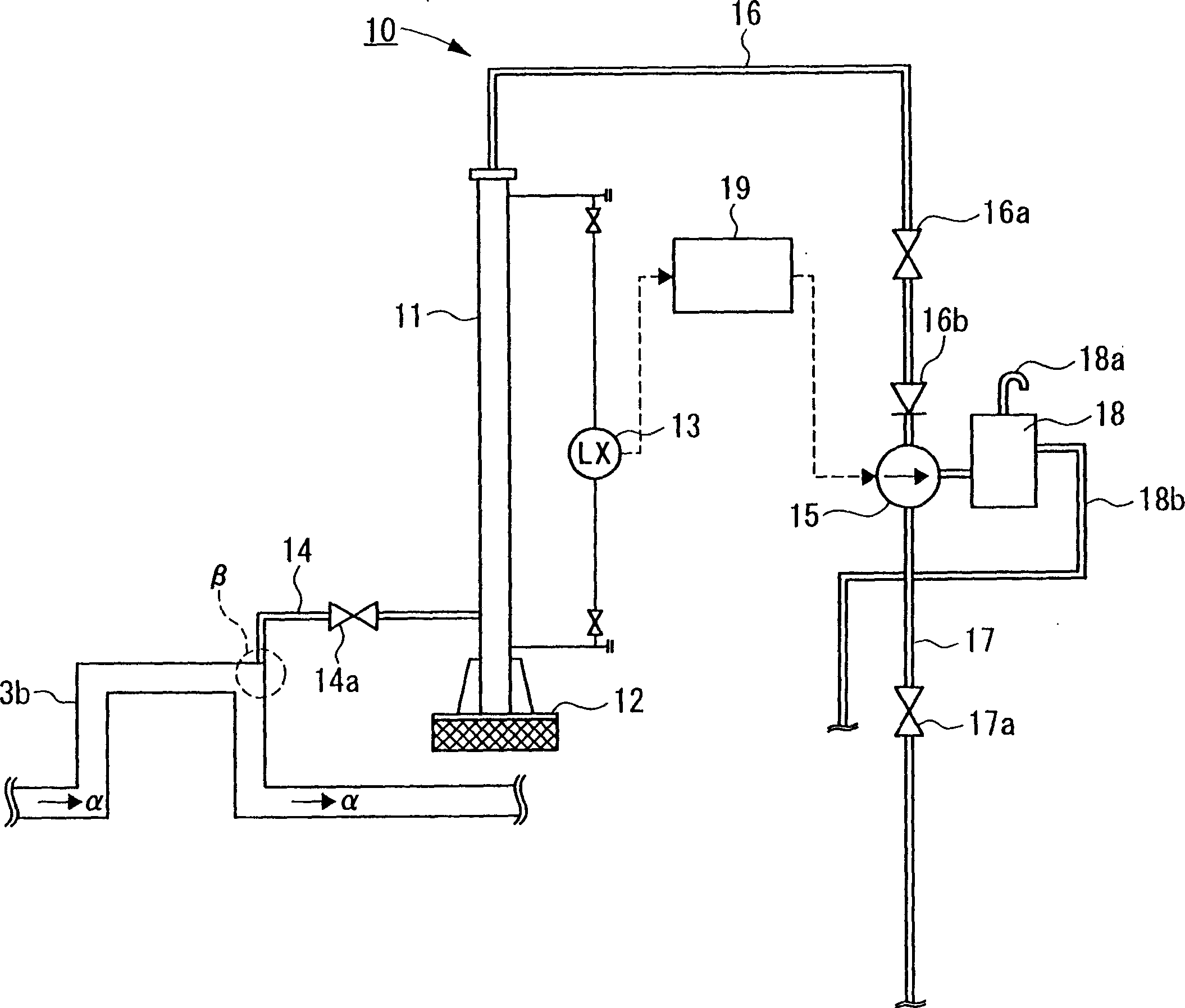
[0041] figure 1 The exhaust device 10 according to the embodiment of the present invention will be described. The air separator pipe 11 of the exhaust device 10 is installed on the ground 12 so as to have an axial direction in a vertical direction. In this embodiment, the length of the air separator pipe 11 is 6 m. The air separator pipe 11 is equipped with a water level detector 13 for detecting the water level of seawater which has flowed into the air separator pipe 11 .

[0042] The lower part of the air separator pipe 11 is connected to the circulating water pipe 3b on the water release side through the connecting pipe 14 . More specifically, the connecting pipe 14 is connected to a portion of the circulating water pipe where the air tank is prone to occur.

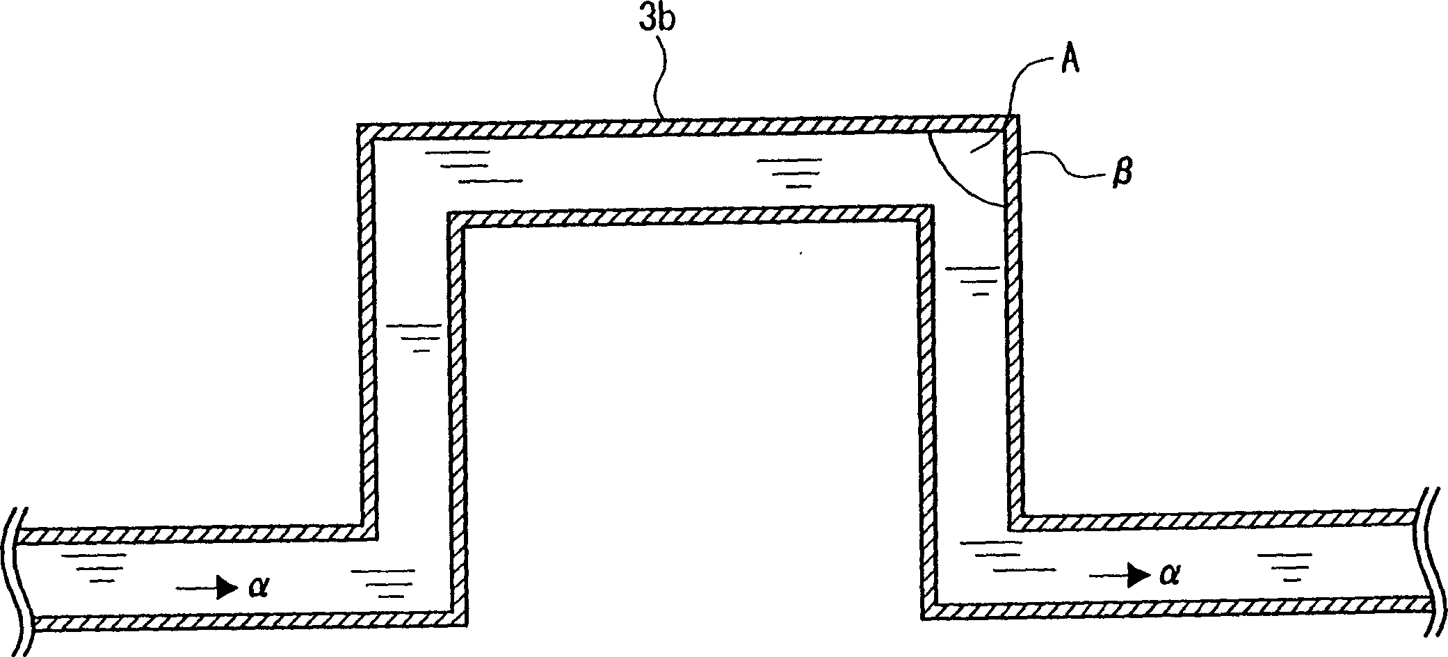
[0043] For example, if the height at which the circulating water pipe 3b is placed is raised along the flow direction of the water and then lowered, (for example, figure 1 α direction), then the air groove is ea...


PUM


Abstract

The circulation water pipe 3b makes circulation water delivered from a condenser of which temperature is raised to flow. The air is easily isolated in a falling part [beta] of the circulation water pipe 3b. An air separator pipe 11 and the part [beta] vertically arranged are connected by a connection pipe 14, and the isolated air is made to flow into the air separator 11. When an amount of the air trapped in the air separator pipe 11 exceeds a set air amount, an air bleed pump 15 is operated, and the trapped air is delivered to the outside. Thus, the occurrence of the trapped air can be prevented in the circulation water pipe 3b, and increase of flow passage resistance or lining peeling can be prevented which is caused by the trapped air.

Description

technical field [0001] The invention relates to an exhaust device for water pipes. More particularly, the present invention relates to an exhaust device for a water pipe designed to prevent the occurrence of a water reservoir in the water pipe by conveniently and easily exhausting air released in the water pipe. Background technique [0002] In thermal power plants, nuclear power plants and hybrid power plants, seawater is often used as cooling water (circulating water) in condensers. [0003] like figure 2 As shown, circulating water (sea water) is drawn from a water suction pit (sea) 2 by a circulating water pump 1, and the drawn circulating water (sea water) is supplied into a condenser 4 through a circulating pipe 3a on the water supply side. In the condenser 4, the exhaust gas from the steam turbine is cooled with circulating water (sea water) to cool the steam in the exhaust gas for the condenser. Circulating water (sea water) whose temperature has increased during ...

Claims


Application Information

Patent Timeline
Patent Type & Authority Applications(China)
IPC IPC(8): F17D1/02F28B9/10
CPCY10T137/3118F16L55/07Y10T137/3084
Inventor 田边浩史桥本安弘
Owner MITSUBISHI POWER LTD
Why Eureka
Try Eureka