Multi-spot combustion engine

An engine and multi-point technology, applied in the direction of engine components, engine ignition, combustion engine, etc., can solve the problem of large room for improvement of the engine, and achieve the effects of increasing flame diffusion speed, improving fuel consumption, and reducing emissions

Inactive Publication Date: 2006-10-04
NISSAN MOTOR CO LTD
View PDF1 Cites 6 Cited by
  • Summary
  • Abstract
  • Description
  • Claims
  • Application Information

AI Technical Summary

Problems solved by technology

In particular, there is a lot of room for improvement in engines that produce squeezed gas

Method used


Image

  • Multi-spot combustion engine
  • Multi-spot combustion engine
  • Multi-spot combustion engine

Examples


Embodiment Construction

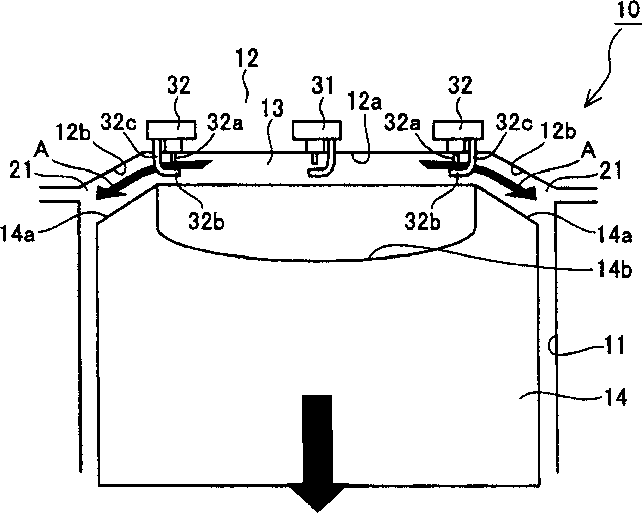
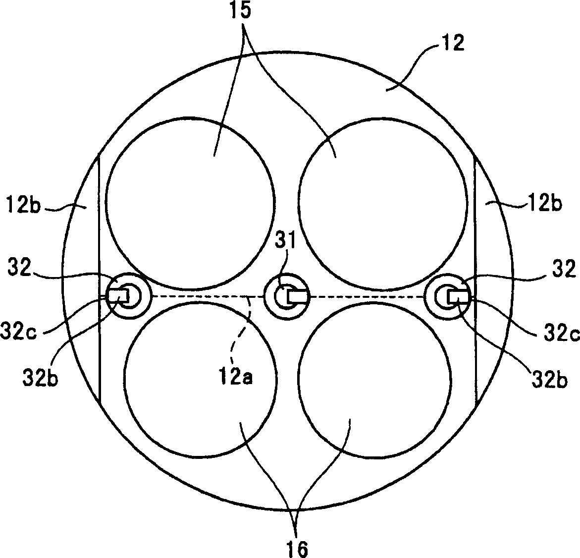
[0020] Figure 1A and 1B The peripheral spark plug arrangement structure of the multi-point ignition engine according to the first embodiment is shown, wherein, Figure 1A is a side elevation view, and Figure 1B is shown in Figure 1A Plan view of the cylinder head in .

[0021] shown in Figures 1A to 1B The multi-point ignition engine 10 in the FIG. 1 includes a combustion chamber 13 , which is constituted by a cylinder block 11 and a cylinder head 12 . The combustion chamber 13 is a ridge-roof type of combustion chamber and is as Figure 1B As shown, the intake valve 15 is provided on one side and the exhaust valve 16 is provided on the other side across the roof ridge line 12a. In addition, the center spark plug 31 and the peripheral spark plug 32 are arranged along the roof ridge line 12a.

[0022] An inclined crown surface 14a that becomes more convex at the center portion of the combustion chamber 13 is formed on the periphery of the crown surface of the piston 14 ...


PUM


Abstract

This multipoint ignition engine comprises a cylinder head 12, a piston 14, a squish generating part 21 formed on the inner wall surface 12b of the cylinder head and the crown surface 14a of the piston, generating normal squish when the piston 14 rises near the top dead center, and generating reverse squish when the piston 14 is lowered near the top dead center, a center plug 31 disposed at the approximately center of the inner wall surface of the cylinder head, and peripheral plugs 32 disposed on the cylinder peripheral side of the center plug 31 on the inner wall surface of the cylinder head, having the leg parts 32c of a grounding electrode positioned on the same side as the squish generating part 21 relative to the electrode 32a, and igniting at such a timing that the squish generated by the squish generating part 21 flows between the center electrode 32a and the grounding electrode 32b.

Description

technical field [0001] The present invention relates to a multi-point ignition engine. Background technique [0002] The multi-point ignition engine disclosed in Japanese Laid-Open Application No. H04-183925 aims to provide combustion stability by providing an ignition spark plug. The placement of the ignition plugs is determined based on the strength of the generated vortex, the distribution of the mixing ratio, and the distribution of the remaining gas. [0003] However, even if the ignition plug is arranged as described above, there is still room for further reduction of emissions such as hydrocarbons HC in the exhaust gas. In particular, there is much room for improvement in engines that generate squeeze gas. SUMMARY OF THE INVENTION [0004] The proposed embodiment of the present invention provides a multi-point ignition engine, which includes: a cylinder head; a piston; and a squish generating portion formed on an inner wall of the cylinder head and a crown surface...

Claims


Application Information

Patent Timeline
Patent Type & Authority Applications(China)
IPC IPC(8): F02P15/02
CPCY02T10/125Y02T10/12
Inventor 井上浩一西井聪森浩一三石俊一
Owner NISSAN MOTOR CO LTD
Why Eureka
Try Eureka