Optical current sensor based on microelectronic mechanical system, making and detecting method thereof

A current sensor and micro-electronic machinery technology, applied in the field of current sensor, can solve problems such as susceptibility to strong magnetic interference, difficulty in practical application, and affecting system performance

Active Publication Date: 2006-10-11
ANHUI CHINA SCI MW ELECTRONIC TECH CO LTD
View PDF0 Cites 33 Cited by
  • Summary
  • Abstract
  • Description
  • Claims
  • Application Information

AI Technical Summary

Problems solved by technology

The optical fiber is used for the light transmission and sensing part of the all-fiber-optic current sensor. Due to the linear birefringence inside the light, it affects the measurement accuracy and long-term stability. Application brings difficulties (Liu Bin, Zhang Junzheng, Li Yubo. Design of a new type of optical fiber current sensor [J]. Acta Metrology, 2003, 24(1): 65-68); bulk optical material current sensors are difficult to process Large size, fragile sensor head, high cost, etc., and the phase shift is inevitably introduced in the process of light reflection, so that the two orthogonal linearly polarized lights become elliptically polarized light, which affects the performance of the system. At the same time, the magneto-optical The change of characteristics with temperature affects the accuracy and stability of sensing (Song J., McLaren P.G., Thomson D.J.A Faraday Effect Based ClamponMagneto-optical Current Transducer for Power Systems[J].IEEE WESCANEX′95 PROCEEDINGS: 329-333.); Conventional photoelectric hybrid current sensors still use conventional CT (Current Transducer, current transformer), and still need a power supply to drive the sensor head on the high-voltage side, which is significantly affected by temperature, and is also susceptible to strong magnetic interference, which cannot overcome the magnetic saturation phenomenon. It can only be used as a transitional scheme from electromagnetic to all-optical OCS (Optical Current Sensor, Optical Current Sensor) (Jiao Binliang, Zheng Shengzhen

Method used


Image

  • Optical current sensor based on microelectronic mechanical system, making and detecting method thereof
  • Optical current sensor based on microelectronic mechanical system, making and detecting method thereof
  • Optical current sensor based on microelectronic mechanical system, making and detecting method thereof

Examples


Embodiment Construction

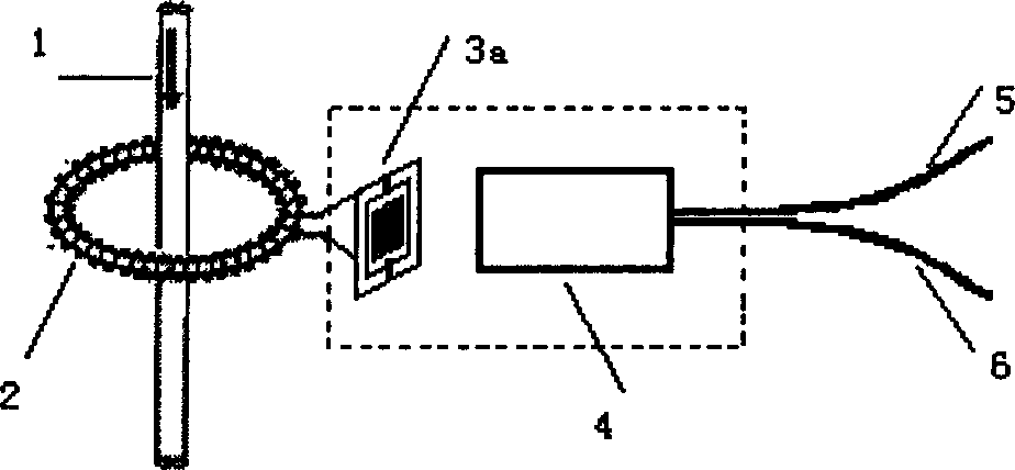
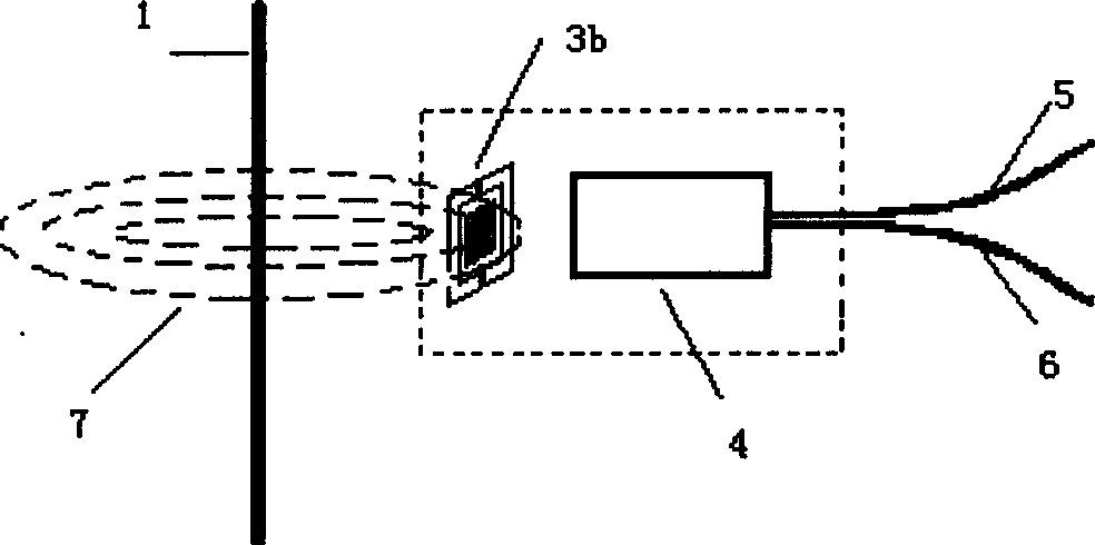
[0040] Taking Rogowski coils in series with helical coil MEMS torsion micromirrors and permanent magnets (NdFeB) to generate magnetic fields as an example to illustrate the implementation steps, in which silicon is used as the substrate material, gold is used as the MEMS coil material, the torsion plane, the metal coil, the torsion The beams are all rectangular:

[0041] 1. Design of parameters

[0042] A. Calculate its resistance, mutual inductance, and self-inductance according to the adjustable Rogowski coil parameters (number of turns, ring diameter, mandrel diameter, wire diameter, etc.).

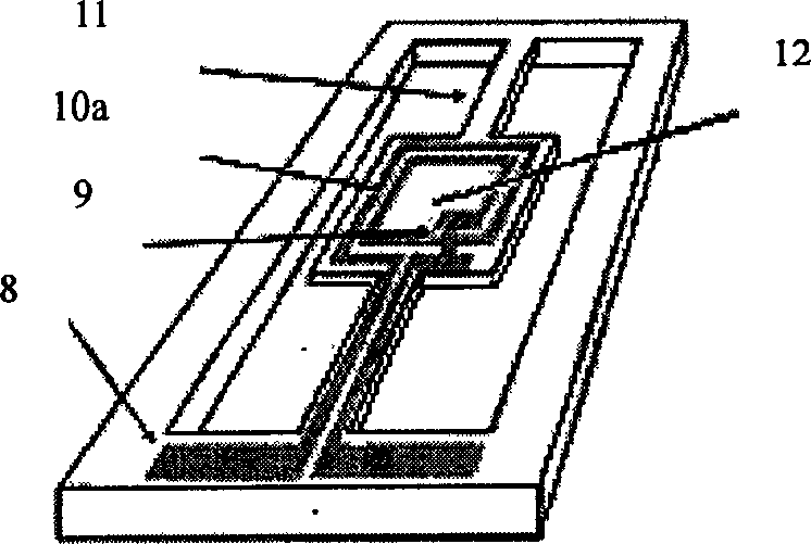
[0043] B. Calculate the moment of inertia and damping according to the initial parameters (length, width, height) of the rotating film.

[0044] C. Calculate the resistance, mutual inductance, and self-inductance of the coil according to the structural parameters of the metal coil (turns, length, width, height, single-turn coil width, and coil spacing) and position parameters (the dis...


PUM


Abstract

The invention relates to an optical current sensor based on micro electric mechanical system. It is characterized in that: it uses micro mechanical technique to prepare the MEMS metallic coil on the MEMS torsion micro lens; the Rogowski coil with non-magnetic skeleton and the MEMS metallic coil will guide the high-voltage alternative-current electric signal as induced current into the coil of MEMS torsion micro lens; a reflector is prepared on the back of MEMS torsion micro lens, which can swing around the axle by the electromagnetic torque; the swing angle can be measured by optical beam couple method that sensitive to the angle to attain the current valve. The invention uses the MEMS technique in the detection of high-voltage and large current, to be driven by induced current, and avoid driving power at the high-voltage end, to realize optical electric separation. It has small volume, lower cost, bath production and anti-disturb ability, with high test accuracy.

Description

technical field [0001] The invention relates to an optical current sensor based on a micro-electromechanical system (MEMS), a manufacturing method and a detection method, and is an optical current sensor used in many industrial technical fields such as electric power to detect alternating large currents. It belongs to the field of current sensors. Background technique [0002] In order to ensure the safe operation of the power system, it is necessary to measure the relevant parameters of the power system and various power equipment in order to carry out necessary measurement, monitoring and protection. Common measurement and protection devices cannot be directly applied to high-voltage, high-current power circuits, but need to transform these power parameters into low-level parameters or signals through transformers in proportion to supply measuring instruments, meters and other similar electrical appliances These devices that transform and measure signals are called curren...

Claims


Application Information

Patent Timeline
Patent Type & Authority Applications(China)
IPC IPC(8): G01R19/02
Inventor 吴亚明赵本刚徐静刘玉菲高翔李四华
Owner ANHUI CHINA SCI MW ELECTRONIC TECH CO LTD
Why Eureka
Try Eureka