

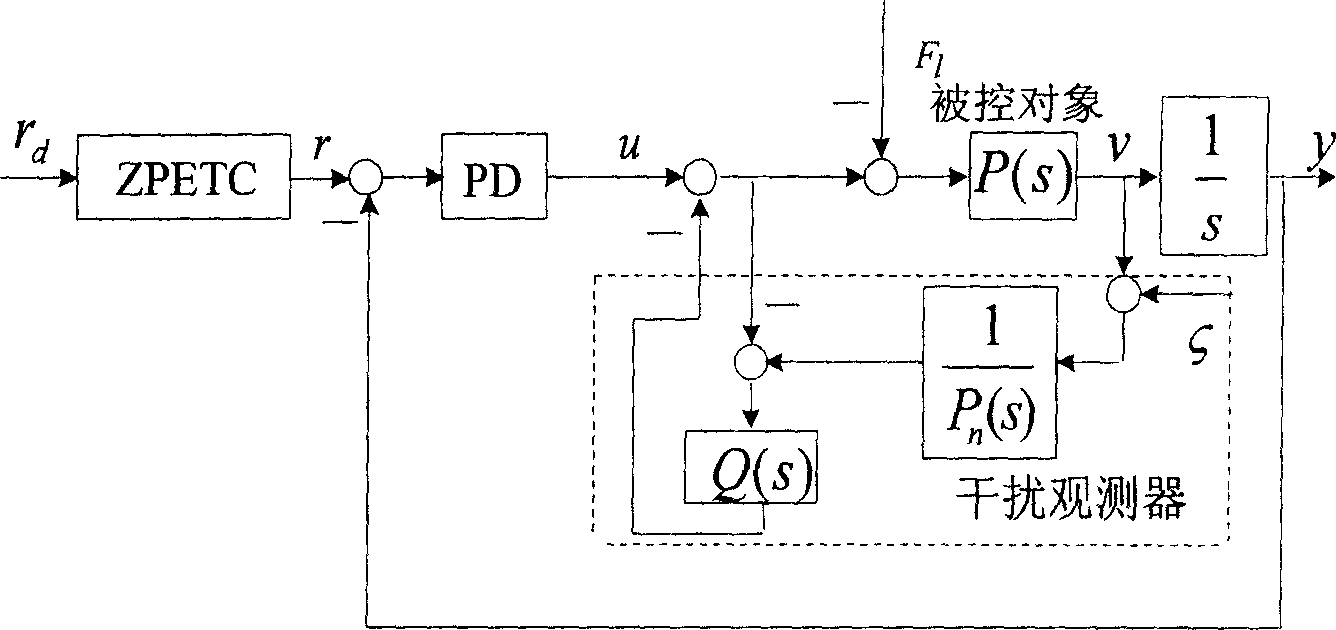
Method for improving contour machining precision by using zero phase error tracking controller and disturbance observer
A zero-phase error and interference observation technology, applied in digital control, electrical program control, etc., can solve problems such as system non-modeling characteristics, system oscillation, and gain limitation
- Summary
- Abstract
- Description
- Claims
- Application Information
AI Technical Summary
Problems solved by technology
Method used
Image

Examples
Embodiment Construction
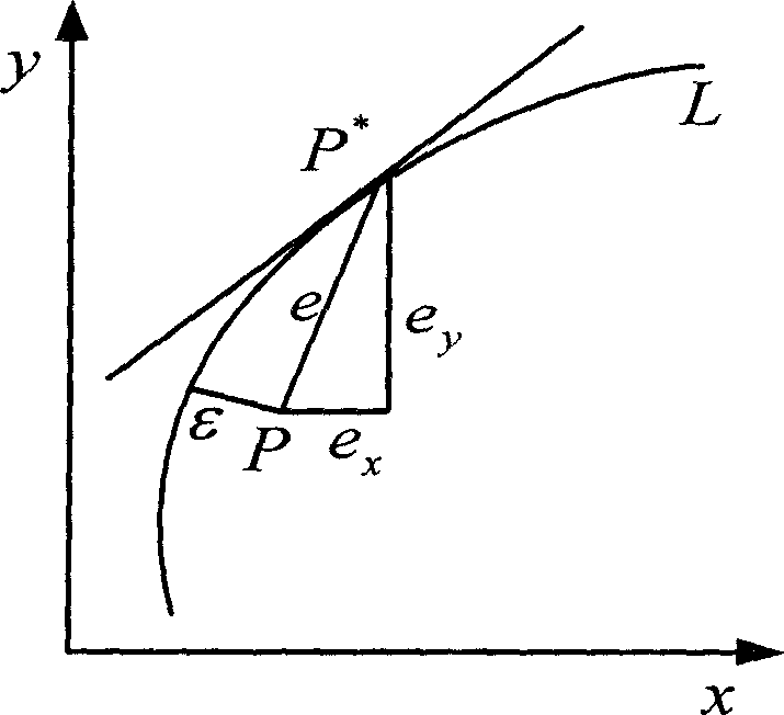
[0144] The present invention processes figure 2 Take the arc track shown as an example, set the system nominal object P n (s)=5 / (0.1s+1).
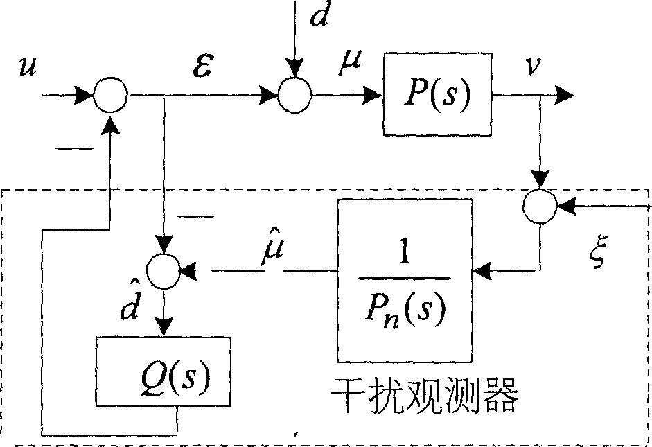
[0145] 1. Design of DOB
[0146] According to the set system nominal object, that is, the speed loop transfer function, the bandwidth of the third-order low-pass filter is continuously changed, as follows:
[0147] Q ( s ) = 3 τs + 1 ( τs ) 3 + 3 ( τs ) 2 + 3 τs + 1
[0148] Reasonably choose the value of τ, here, choose τ=1 / 260, the sampling...
PUM
 Abstract
Description
Claims
Application Information