Guide wire

A technology for guide wires and guide wire parts, applied in catheters, guide wires, surgery, etc., can solve problems such as inability to improve the bonding strength of guide wire parts, difficulty in obtaining torque transmission, troublesome connection operations of guide wire parts, etc., and achieve excellent Operability, avoiding stress concentration on welded parts, preventing sudden bending (bending) or twisting effect

Inactive Publication Date: 2006-10-18
TERUMO KK
View PDF2 Cites 15 Cited by
  • Summary
  • Abstract
  • Description
  • Claims
  • Application Information

AI Technical Summary

Problems solved by technology

[0016] Although such a guide wire can be equipped with guide wire parts with desired characteristics on its front end side and base end side, but because it connects the two guide wire parts through a tubular connecting member, there is a prob

Method used


Image

  • Guide wire
  • Guide wire
  • Guide wire

Examples


Embodiment Construction

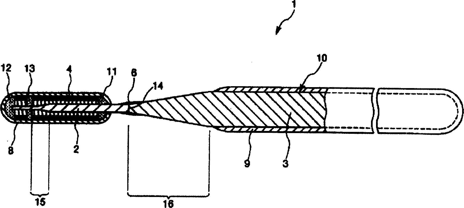
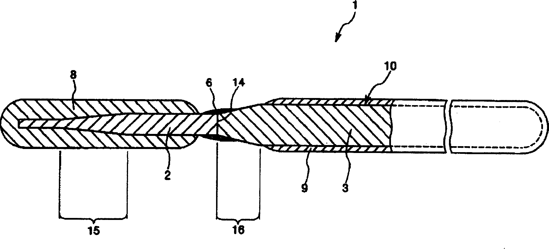
[0075] The guide wire of the present invention will be described in detail below according to the preferred embodiments shown in the accompanying drawings.

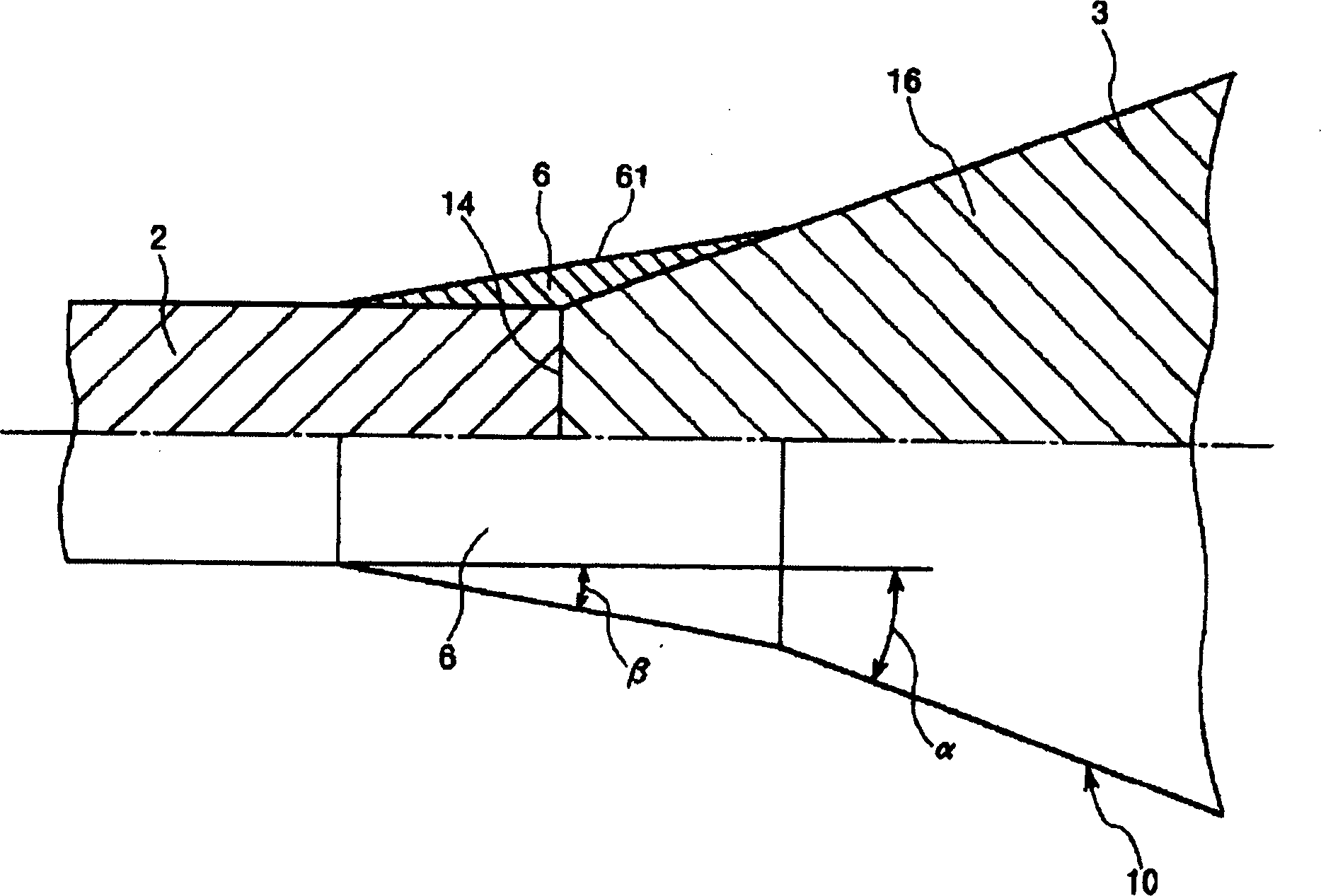
[0076] figure 1 is a longitudinal sectional view showing an embodiment of the guide wire of the present invention; figure 2 It is an enlarged longitudinal sectional view showing the vicinity of the joint portion of the guidewire main body in the guidewire of the present invention. Moreover, for the convenience of illustration, figure 1 as well as figure 2 The right side is the "base end" and the left side is the "front end". In addition, in figure 1 as well as figure 2 In , the length in the longitudinal direction of the guide wire is shortened for easy understanding, and the dimension in the thickness direction of the guide wire is shown in an exaggerated manner, and the ratio of the dimension in the longitudinal direction to the dimension in the thickness direction is different from the actual situation.

[007...


PUM

PropertyMeasurementUnit
The average thicknessaaaaaaaaaa

Abstract

A wire having excellent operability while ensuring flexibility at the distal end, and having improved bonding strength between a first wire part and a second wire part. It has a wire main body including a linear first wire part arranged on the distal side and a linear second wire part arranged on the proximal side of the first wire part. A coil having X-ray contrast properties is preferably provided on the outer periphery of the distal end portion of the first guide wire portion. The base end portion of the first guide wire part preferably has a constant outer diameter everywhere along its length direction, and the front end part of the second guide wire part preferably has a tapered part whose outer diameter gradually increases from the front end to the base end direction. constitute. Preferably, the outer diameter of the proximal end of the first wire guide part and the outer diameter of the distal end of the second guide wire part are the same. The outer diameters of the two guide wire parts are joined by welding on the same end surface, and a metal covering layer is preferably formed on the outer periphery of the joint part to relax the outer peripheral surface of the base end part of the first guide wire part and the outer peripheral surface of the taper part. Angle difference between.

Description

technical field [0001] The present invention relates to a guide wire, and more particularly to a guide wire used for guiding a catheter into body cavities such as blood vessels and bile ducts. Background technique [0002] For example, such as PTCA (Percutaneous Transluminal Coronary Angioplasty: percutaneous coronary angioplasty), the treatment of difficult-to-operate parts, or the treatment for the purpose of reducing damage to the human body, or the examination of cardiac angiography, etc. With catheters, a guide wire is used to guide the catheter. Regarding this guide wire for PTCA, when using it, in the state where the tip of the guide wire protrudes from the tip of the balloon catheter, the guide wire and the balloon catheter are inserted into the vicinity of the narrowed part of the blood vessel at the target site, and the guide wire Guide the tip of the balloon catheter to the vicinity of the narrowed part of the blood vessel. [0003] In addition, in the treatment...

Claims


Application Information

Patent Timeline
IPC IPC(8): A61M25/09A61B1/00A61M25/01
Inventor 田野丰梅野昭彦
Owner TERUMO KK
Why Eureka
Try Eureka