Soldering method, soldering device, bonding method, bonding device, and nozzle unit

A brazing method and brazing technology, applied in brazing, can solve problems such as nozzle 402 opening 403 blocking

Inactive Publication Date: 2006-10-18
TDK CORPARATION
View PDF2 Cites 14 Cited by
  • Summary
  • Abstract
  • Description
  • Claims
  • Application Information

AI Technical Summary

Problems solved by technology

Furthermore, the opening 403 of the nozzle 402 may be clogged due to adhered solder

Method used


Image

  • Soldering method, soldering device, bonding method, bonding device, and nozzle unit
  • Soldering method, soldering device, bonding method, bonding device, and nozzle unit
  • Soldering method, soldering device, bonding method, bonding device, and nozzle unit

Examples


Embodiment 1

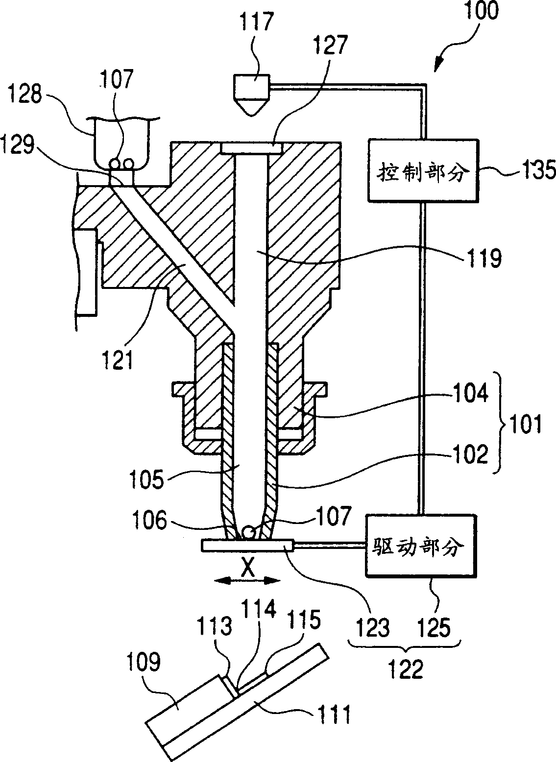
[0033] Figure 1A with 1B is a partial cross-sectional view of a brazing device according to an embodiment of the present invention; in Figure 1A With the shutter in the closed position, the device described in Figure 1B The midgate is in the open position. exist Figure 1A with 1B In the device of the illustrated embodiment, the electrical connection is made between a substantially rectangular head slider 109 to which a flexure 111 in the form of a thin plate will be attached by means of solder, or solder balls 107 .

[0034] First, the structure of the slider 109 and the bender 111 to be brazed will be explained. On the surface of one end portion of the slider 109, a slider electrode 113 formed of a metal plate is provided. A bender electrode 115 formed of a metal plate is provided on the bender 111, and the slider electrode 113 and the bender electrode 115 form a corner portion 114 at an angle of about 90 degrees. The molten solder ball 107a is adhered to a positi...

Embodiment 2

[0053] Although the opening / closing portion 122 is employed in the above-described Embodiment 1, holding and releasing of the solder balls can also be achieved by employing a suction device. Next, Embodiment 2 using a suction device will be described.

[0054] Fig. 3 is a sectional view of a part of a brazing apparatus having a suction device. Except for the components shown in FIG. 3 , the (other) components of the brazing apparatus of this embodiment are the same as those of the brazing apparatus in FIG. 1 , since FIG. 3 does not show components common to these embodiments. The nozzle 152 has a suction hole 187 near the opening 156 . The suction hole 187 extends horizontally through the wall of the nozzle 152 (as shown in FIG. 3 ), and communicates with the receiving portion 155 . In addition, one end of the suction pipe 174 is connected to the suction hole 187 . A suction device, that is, a suction device 175 generating a suction force is communicated to the other end of...

Embodiment 3

[0061] Next, a soldering apparatus according to Embodiment 3 of the present invention in which compressed gas is applied to the solder to spray the solder will be explained. Fig. 4 is a partial sectional view of a brazing apparatus according to Embodiment 3 of the present invention.

[0062] The slider 1151 and the bender 1155 to be brazed to each other are arranged such that the slider electrode 1153 and the bender electrode 1157 are at an elevation angle of substantially 90 degrees. There are at least four slider electrodes and four flexure electrodes. Temporary positioning of the slider 1151 and the bender 1155 is achieved by cement or a clamping mechanism, and the slider electrode 1151 and the bender 1155 form a groove 1159 at an elevation angle of approximately 90 degrees. The brazing nozzle 1102 is positioned so that the nozzle substantially corresponds to the center position of the groove 1159 in the width direction (the direction perpendicular to the plane of FIG. 4 )...


PUM

PropertyMeasurementUnit
diameteraaaaaaaaaa

Abstract

Provided is a nozzle unit for use in a bonding device in which bonding between a first member and a second member is effected by providing a bonding member that has been melted by heating at a bonding position where the first member and the second member are to be bonded to each other. The nozzle unit includes: a cylindrical nozzle assembly having an accommodating space accommodating the bonding member, and an opening which allows ejection of the bonding member accommodated in the accommodating space onto the bonding position, which has a diameter larger than the diameter of the bonding member, and which communicates with the accommodating space; and a holding/releasing member for releasably holding the bonding member within the accommodating space.

Description

technical field [0001] The present invention relates to a joining method and joining apparatus for joining a first element to a second element using a joint. Background technique [0002] During the manufacturing process of the magnetic head, the joint between the magnetic head slider electrode and the flexure electrode is achieved by soldering using solder balls. More specifically, two electrodes were arranged at an angular interval of 90 degrees, and a solder ball was placed between the two electrodes. The solder balls are melted by heat radiation or other similar methods to achieve electrical connection between the two electrodes. Next, a conventional solder ball soldering apparatus will be described with reference to the drawings. [0003] FIG. 9 shows a partial sectional view of a suction nozzle for brazing using a conventional brazing device 300 . In FIG. 9, reference numeral 309 denotes a substantially parallelepiped slider, and reference numeral 311 denotes a curv...

Claims


Application Information

Patent Timeline
Patent Type & Authority Applications(China)
IPC IPC(8): B23K1/005B23K3/04B23K3/06B23K3/08G11B5/33H01L21/60H01R4/02H05K3/34
CPCH01L2224/742
Inventor 和合达也水野亨进藤修
Owner TDK CORPARATION
Why Eureka
Try Eureka