U-shaped afterheat utilizing annealing furnace below roller

A roller hearth type annealing furnace technology, which is applied to heat treatment furnaces, furnaces, furnace types, etc., can solve the problems that the waste heat of the workpiece cannot be fully utilized, the number of trays should not be too large, and the microstructure dispersion is large. Small deformation, reduced heat dissipation area, and improved utilization

Active Publication Date: 2006-10-18
HANGZHOU JINZHOU TECH CO INC
View PDF0 Cites 20 Cited by
  • Summary
  • Abstract
  • Description
  • Claims
  • Application Information

AI Technical Summary

Problems solved by technology

The amount of furnace loading is large; the push rod continuous furnace also heats the material tray while heating the workpiece, which consumes a lot of energy; the number of material trays cannot be too many, and the process cycle is long; the microstructure in the same furnace has large dispersion and the product is uniform Poor performance

Method used


Image

  • U-shaped afterheat utilizing annealing furnace below roller

Examples


Embodiment Construction

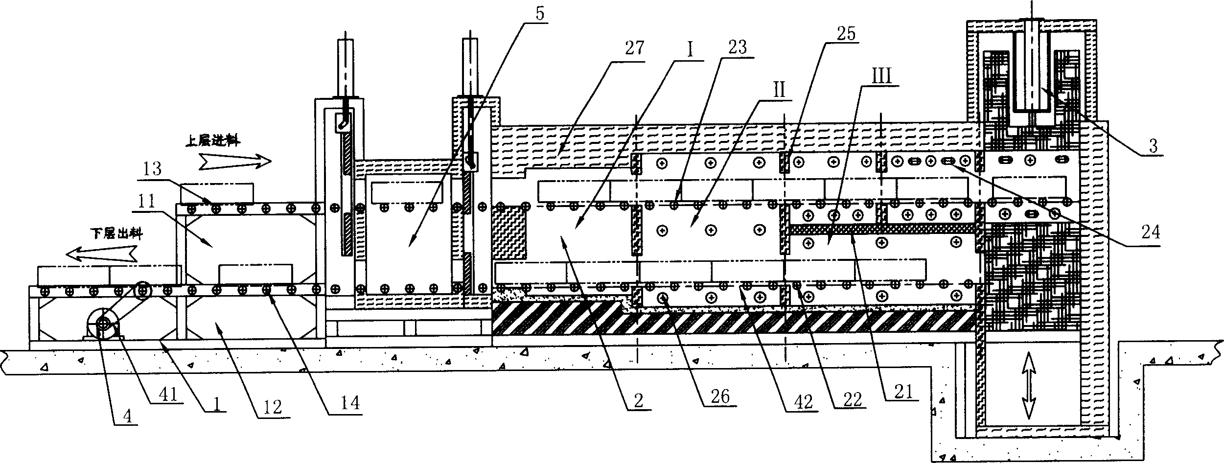
[0024] Such as figure 1 Shown is a schematic structural view of the roller hearth U-shaped waste heat utilization annealing furnace of the present invention. Including feeding and discharging table 1, roller hearth furnace 2, lifting mechanism 3, transmission system 4 and vacuum ventilation chamber 5, feeding and discharging table 1, vacuum ventilation chamber 5, roller hearth furnace 2 and lifting mechanism 3 are connected in sequence, and the roller hearth furnace 2 is provided with a heat insulating layer 21, which separates a part of the roller hearth furnace 2 into an independent furnace upper layer and a furnace lower layer. One of the racks 12 is arranged on the upper floor, and the other is arranged on the lower floor. The transmission system 4 includes a motor 41 and a transmission device 42. The motor 41 is connected to the transmission device 42. The lower layer and the upper layer of the roller hearth furnace 2 are respectively provided with a number of lower roll...


PUM


Abstract

The U-shaped afterheat utilizing annealing furnace below roller includes a material stage, a furnace below roller, an elevating mechanism, a transmission system and a vacuum changing chamber. Heat insulating layer is set inside the furnace below roller to separate the furnace into independent upper part and lower part for simultaneous heat treatment of metal workpiece in high treating amount. The present invention utilizes afterheat to raise the energy utilization rate and has no air convection to reduce oxidation and decarbonization of metal workpiece.

Description

【Technical field】 [0001] The present invention relates to metal heat treatment, in particular to metal heat treatment equipment. 【Background technique】 [0002] Metal heat treatment is a process in which metal workpieces are heated to a suitable temperature in a certain medium, and after being kept at this temperature for a certain period of time, they are cooled at different rates. Metal heat treatment is one of the important processes in mechanical manufacturing. Compared with other processing techniques, heat treatment generally does not change the shape and overall chemical composition of the workpiece, but changes the microstructure inside the workpiece or changes the chemical composition of the surface of the workpiece. , to give or improve the performance of the workpiece. It is characterized by improving the intrinsic quality of the workpiece, which is generally not visible to the naked eye. In order to make metal workpieces have the required mechanical properties,...

Claims


Application Information

Patent Timeline
IPC IPC(8): C21D9/00C21D1/26
Inventor 范本良
Owner HANGZHOU JINZHOU TECH CO INC
Why Eureka
Try Eureka