

Wind driven engine with combined wind cups and blades
A wind turbine and combined technology, which is applied in the field of combined wind cup blade wind turbines, can solve the problems of backward development, cost reduction adaptability, wind catching ability, control mode, performance-price ratio and inconvenient promotion, and achieve start-up Good performance, simple shape, cost reduction effect
- Summary
- Abstract
- Description
- Claims
- Application Information
AI Technical Summary
Problems solved by technology
Method used
Image

Examples
Embodiment 1
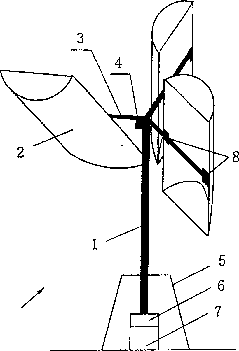
[0022] Such as figure 1 As shown, select a common combination method of a rectangular wind cup blade wind turbine of the present invention: use a section of hollow main shaft (1) to install vertically through a ground fixing device (5), connect a flexible flange and then connect to the transducer The main shaft of the mechanism (7). A set of support arms (3) is installed on the upper end of the main shaft (1) so that it is perpendicular to the main shaft (1) and the three are at an average angle of 120° to each other. Oil pipes and control lines are connected to the controlled electro-hydraulic control device (6) and hydraulic brake device on the main shaft. Bearings, limit stops, piston hydraulic buffer parts, and movable brackets (8) are installed on the three support arms (3), and then a piece of lightweight wind cup blade (2) is connected respectively so that the axis of rotation of the bracket is aligned with the wind cup. The rectangular midline connections of the blad...
Embodiment 2
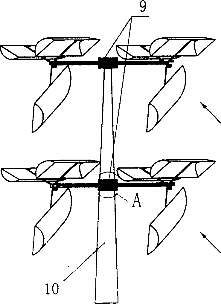
[0026] Such as figure 2 As shown, select the wind cup blade wind turbine main shaft to be installed and combined with the vertical rod or tower fixing device in a horizontal manner: install the rod or tower (10) on the rotary body, such as Figure 4 (A), the combined main shaft (1), connects the energy-transforming mechanical main shaft on the revolving body in a horizontal manner, the main shaft axis (18) and the center are eccentric to the shaft or tower axis (17). The connecting arms, brackets, and fan blades are the same as those in Embodiment 1, and will not be repeated here. When the wind comes from any direction, since the main shaft transmits the wind force to the eccentric rotator connected to the pole tower, the wind turbine will rotate to the downwind position and automatically align with the wind direction, so that the wind cup blade wind turbine combined with the main shaft in a horizontal manner can automatically face the wind . The horizontal combination meth...
Embodiment 3
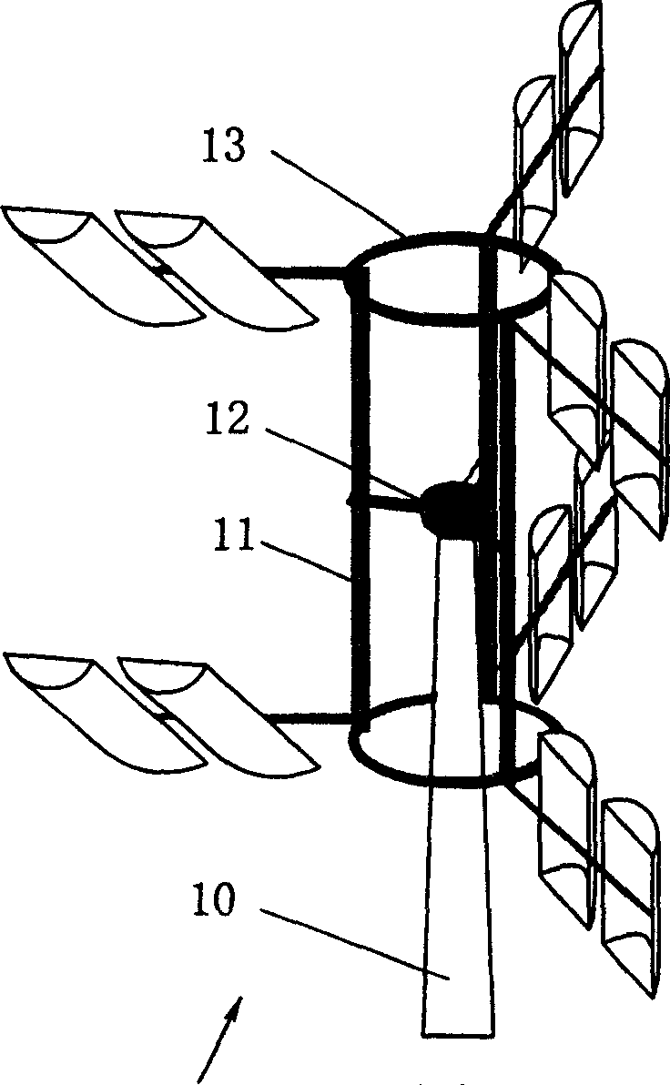
[0028] Such as image 3As shown, the selection of the main shaft of the wind turbine with cup blades to be installed in a vertical manner with a vertical rod or tower fixing device is actually an extension of the ordinary combination method, but it is meaningful for large-scale reduction of costs. The main shaft (1) stands in the vertical rod or tower fixing device (10), its lower end is connected to a flexible flange and then connected to the main shaft of the energy conversion machine (7), and its upper end is connected to the tripod-shaped bracket through the rod or tower bearing (11), (12), (13), the tripod-shaped support connects the support arm (3). And the controlled electro-hydraulic control device (6) on the upper end of the main shaft (1) is connected with the high-pressure oil pipe and the control line to the hydraulic regulator (4) of the support arm rotation, and the hydraulic brake device is installed on the lower end of the main shaft. The connecting arms, brac...
PUM
 Abstract
Description
Claims
Application Information