Supercharge Your Innovation With Domain-Expert AI Agents!

Swash plate compressor

A swash plate and compressor technology, which is applied to liquid variable capacity machinery, mechanical equipment, engine components, etc., can solve problems such as affecting the sliding part of the compressor

Inactive Publication Date: 2006-10-18
TOYOTA IND CORP
View PDF2 Cites 2 Cited by
  • Summary
  • Abstract
  • Description
  • Claims
  • Application Information

AI Technical Summary

Problems solved by technology

The detached film sheets become impurities in the compressor, which may affect the various sliding parts of the compressor

Method used


Image

  • Swash plate compressor
  • Swash plate compressor
  • Swash plate compressor

Examples


Embodiment Construction

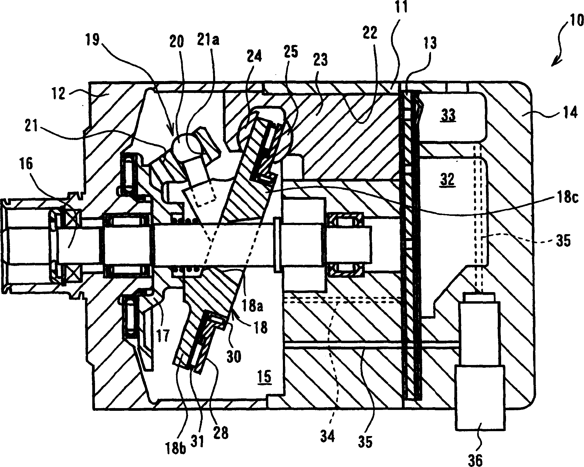
[0021] Refer below figure 1 and 2 A first preferred embodiment of the swash plate compressor according to the present invention will be described. figure 1 A longitudinal sectional view of a single-head piston type variable displacement swash plate compressor 10 is shown. figure 1 The left and right sides of the compressor 10 shown in FIG. 10 correspond to the front and rear sides of the compressor, respectively.

[0022] Such as figure 1 As shown, the compressor 10 includes a cylinder block 11 , a front casing 12 fixedly connected to the front end of the cylinder block 11 , and a rear casing 14 fixedly connected to the rear end of the cylinder block 11 through a valve plate assembly 13 . The cylinder block 11 , the front housing 12 and the rear housing 14 together form a housing assembly of the compressor 10 .

[0023] A crankcase 15 is formed between the cylinder block 11 and the front housing 12 in the housing assembly. A drive shaft 16 is rotatably supported at the ce...


PUM


Abstract

A swash plate compressor includes a housing that has a cylinder bore and rotatably supports a drive shaft. A swash plate is operatively coupled to the drive shaft for rotation therewith. A piston is accommodated in the cylinder bore for reciprocating movement. First and second spaced shoes are fitted to the piston on a side adjacent to the cylinder bore and on a side away from the cylinder bore, respectively, for coupling the piston to the swash plate. The rolling body is mounted on the swash plate through a bearing and in slide contact with the first shoe. A surface of the rolling body in slide contact with the first shoe or a surface of the first shoe in slide contact with the rolling body has a diamond-like carbon film. A surface of the rolling body in rolling contact with the bearing exposes a base material of the rolling body.

Description

technical field [0001] This invention relates generally to a swash plate compressor, and more particularly to a mechanism for converting rotation of the swash plate into reciprocating motion of the pistons. Background technique [0002] For example, Unexamined Japanese Patent Application Publication No. 8-28447 discloses a conventional variable displacement swash plate compressor for compressing refrigerant gas. According to this publication, the compressor has a single-headed piston 22 slidably accommodated in each cylinder bore 1 a, and a pair of spherical shoes 23A, 23B fitted to the neck of the single-headed piston 22 . The swash plate 15 has a boss portion formed on the back thereof, and a thrust bearing 20 is mounted to the boss portion via bearing races 20a, 20b on the front and rear sides of the bearing 20, respectively. The bearing race 20 a is in contact with the swash plate 15 . The swash plate 15 and the thrust bearing 20 are inserted between the shoes 23A, 23B...

Claims


Application Information

Patent Timeline
Patent Type & Authority Applications(China)
IPC IPC(8): F04B27/08C23C4/00C23C16/27
CPCF04B27/1054F04B27/1063F05C2201/0433F05C2203/0882F05C2253/12F04B27/1045F04B27/0878F04B27/0886F05B2210/12F05B2210/14Y10S417/00
Inventor 深沼哲彦杉浦学杉冈隆弘今井崇行
Owner TOYOTA IND CORP
Features
  • R&D
  • Intellectual Property
  • Life Sciences
  • Materials
  • Tech Scout
  • Unparalleled Data Quality
  • Higher Quality Content
  • 60% Fewer Hallucinations
Learn More