
Control circuit for the switch in a switching power supply

A technology for control circuits and switching power supplies, applied in control/regulating systems, electrical components, regulating electrical variables, etc., can solve the problems of increasing the cost, complexity and required space of control circuits, saving terminals and improving voltage control. Effect

Inactive Publication Date: 2006-10-18
FRIWO MOBILE POWER GMBH
View PDF5 Cites 4 Cited by
  • Summary
  • Abstract
  • Description
  • Claims
  • Application Information

AI Technical Summary

Problems solved by technology

This increases the cost, complexity, and space required for the control circuitry

Method used


Image

  • Control circuit for the switch in a switching power supply
  • Control circuit for the switch in a switching power supply
  • Control circuit for the switch in a switching power supply

Examples


Embodiment Construction

[0035] The present invention will be described in more detail below by means of the embodiments shown in the accompanying drawings. Identical and corresponding components are denoted by the same reference numerals in the figures.

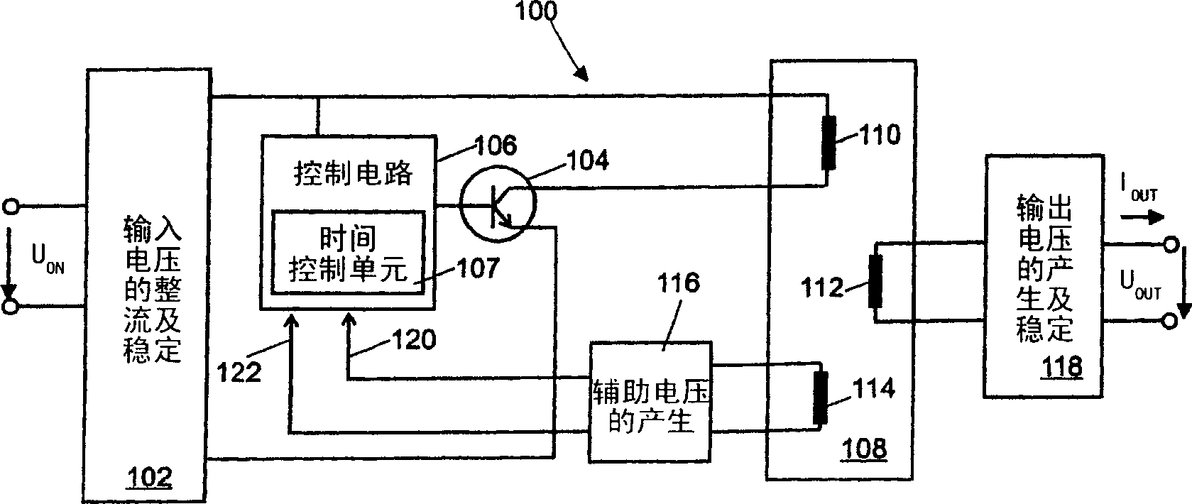
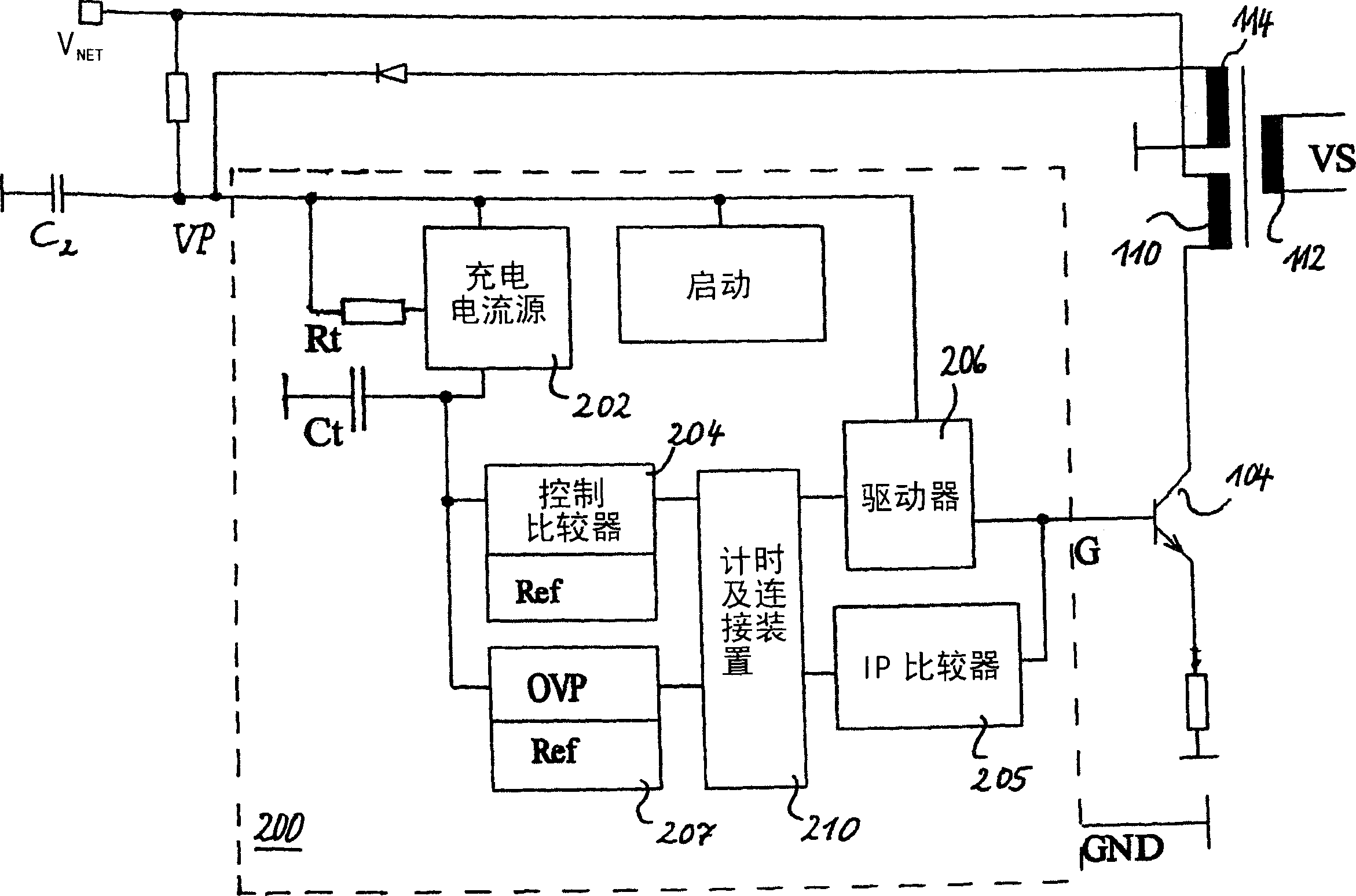
[0036] figure 1 A block diagram of a switched mode power supply 100 with a control circuit 106 is schematically shown. A switching power supply is biased at its input by an AC voltage V net. In Europe the mains voltage varies between 180V and 264V AC and in the US it varies between 90V and 130V AC. In block 102, the input voltage is amplified and stabilized. This ensures that interference signals generated in the switching power supply do not return to the AC voltage network. The primary side winding 110 of the isolation transformer 108 and the primary side switch 104 form a series circuit, which in this example is a power transistor, and the series circuit is connected to the rectified input voltage. According to the control signal of the con...


PUM


Abstract

The present invention relates to a control circuit and related method for controlling the output voltage of a controllable switching power supply. The switching power supply includes a primary-side switch and a transformer with auxiliary windings. After the primary-side switch is turned on, an auxiliary voltage that reflects the output voltage is induced in the auxiliary winding. The induced voltage is input to the control circuit as a control variable. In order to provide a control circuit that requires as few external components as possible, can be manufactured at low cost and requires as little space as possible, the driver output of the control circuit is connected to the control input of the primary side switch, the control circuit is designed as The switching frequency of the primary-side switch is adjusted by the auxiliary voltage, wherein the correlation constant factor between the switching frequency and the auxiliary voltage is selected, so that the output current of the switching power supply selects a preset value, and the driver output terminal is also connected to the comparator input to determine the current through this primary side switch.

Description

technical field [0001] The invention relates to a control circuit and a related method for controlling the output voltage of a controllable switching power supply. The switching power supply includes a primary-side switch and a transformer with an auxiliary winding (winding). After the primary-side switch is turned on, an auxiliary voltage reflecting an output voltage is induced in the auxiliary winding. The voltage induced in the auxiliary winding is provided as a control variable to the control circuit. The invention also relates to a related switching power supply. Background technique [0002] Typically, known switching power supplies use power transistors as switches to provide pulsed current to a network of inductive and capacitive energy storage elements that convert the switched current pulses into a controlled DC voltage. Depending on the mode of operation of the switching power supply, the switching power supply can provide an output voltage that is greater than,...

Claims


Application Information

Patent Timeline
Patent Type & Authority Applications(China)
IPC IPC(8): H02M3/335
Inventor 拉尔弗·施罗德·吉南特·伯格格尔
Owner FRIWO MOBILE POWER GMBH
Learn More