Triangular rotor hydraulic pump

A triangular, hydraulic pump technology, applied in the field of rotor hydraulic pumps, can solve the problems of poor self-priming ability and oil pollution sensitivity of vane pumps, and achieve the effects of stable rotation, strong self-priming ability and high efficiency

Inactive Publication Date: 2006-10-25
SHAANXI UNIV OF SCI & TECH
View PDF0 Cites 12 Cited by
  • Summary
  • Abstract
  • Description
  • Claims
  • Application Information

AI Technical Summary

Problems solved by technology

However, the vane pump has poor self-priming ability and is sensitive to oil pollution, which limits its application in some occasions.

Method used


Image

  • Triangular rotor hydraulic pump
  • Triangular rotor hydraulic pump
  • Triangular rotor hydraulic pump

Examples


Embodiment Construction

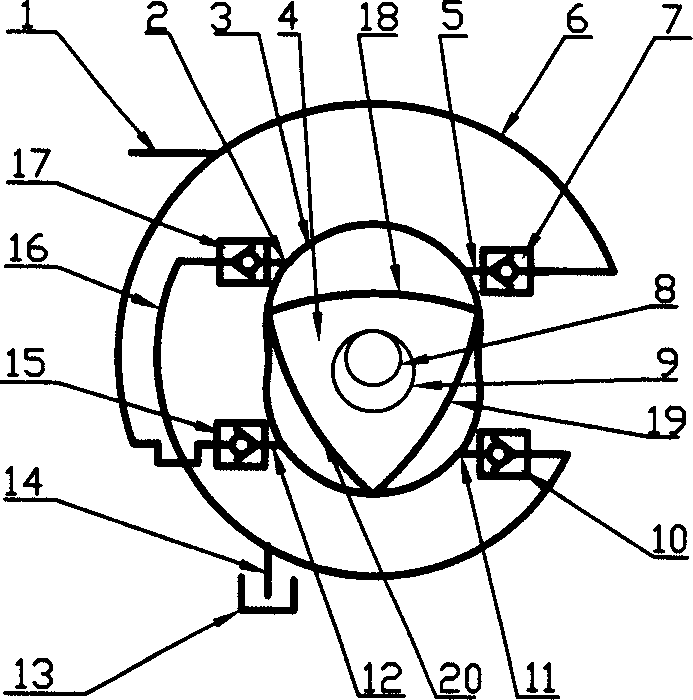
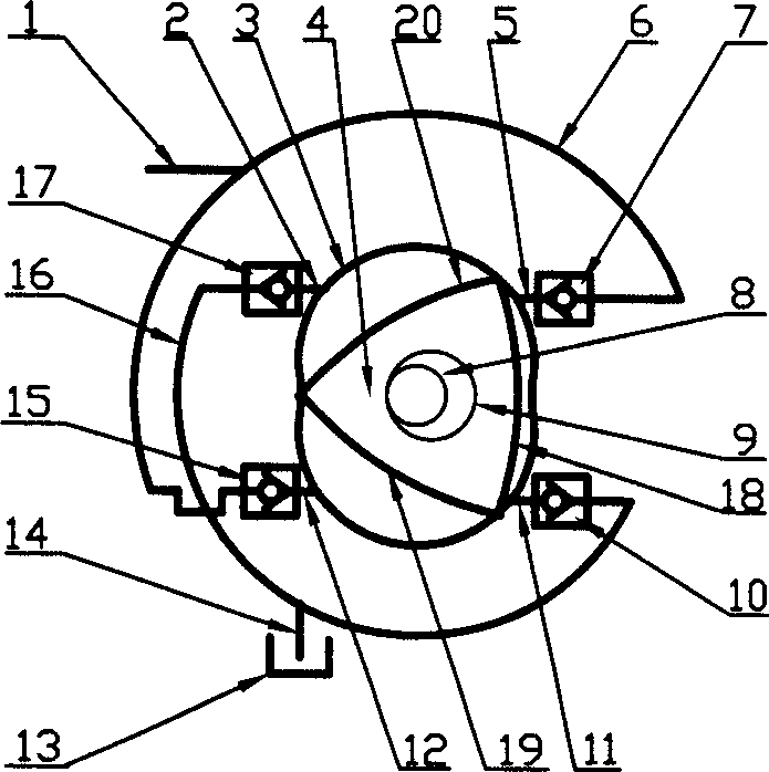
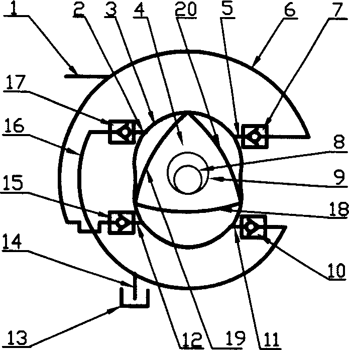
[0011] The structural principle and working principle of the present invention will be further described in detail below in conjunction with the accompanying drawings.

[0012] see figure 1 , the present invention is composed of a stator 3 and a rotor 4, the inner cavity of the stator 3 is an "8"-shaped hysteroidal curve surface, and an oil inlet 2, an oil inlet 11, an oil outlet 5 and an oil outlet 12 are opened on it. . The oil inlets 2 and 11 are connected to the oil inlet groove 16 through the oil inlet check valves 17 and 10 respectively, and the oil suction port 14 on the oil inlet groove 16 communicates with the oil tank 13 . The oil outlets 5 and 12 are respectively connected to the oil outlet 6 through the check valve oil outlets 7 and 15, and the oil outlet 6 communicates with the pressure oil port 1. The oil inlet groove 16 and the oil outlet groove 6 are not communicated with each other, and each constitutes an independent passage. The rotor 4 is in the shape of...


PUM


Abstract

The invention relates to triangle rotor hydraulic pump. It includes stator and rotor. The stator is set oil inlet and outlet. They are respectively connected to oil-in and oil-out grooves. The inner cavity of the stator is formed '8'shape. The rotor is formed equilateral triangle. Thus its three angles can keep good touch with the stator inner cavity while turning. It has good leakproofness, and little noise. And it has better efficiency because of six times oil extraction and pressing per rotation for rotor.

Description

technical field [0001] The invention relates to a rotor hydraulic pump, in particular to a triangular rotor hydraulic pump. Background technique [0002] The rotor hydraulic pump is a device that can provide hydraulic energy with a certain flow and pressure or a lubricating oil source for circulating lubrication in hydraulic systems and mechanical transmissions. Existing hydraulic pumps mainly include gear pumps, vane pumps and plunger pumps. The vane pump belongs to a kind of rotor pump, which is mainly composed of rotor, stator, vane and other parts. The stator has a cylindrical inner surface, and there is an eccentric distance between the stator and the rotor. The blades are installed in the grooves on the rotor and can slide flexibly in the grooves. When the rotor rotates, due to the centrifugal force and the pressure oil at the blade root, the top of the blade is close to the inner surface of the stator, so that several sealed and variable-volume working chambers are ...

Claims


Application Information

Patent Timeline
Patent Type & Authority Applications(China)
IPC IPC(8): F04C2/22
Inventor 陆赤音郭红利
Owner SHAANXI UNIV OF SCI & TECH
Why Eureka
Try Eureka