
Generalized cycloidal active-tooth transmission

A technology of movable tooth transmission and cycloid, which is applied in the direction of gear transmission, transmission device, belt/chain/gear, etc., can solve the problem that the development and production of movable tooth transmission cannot be smoothly applied, it is not conducive to improving the dynamic performance of the device, and it has not been obtained in the industry To achieve the effect of improving manufacturability and transmission performance, excellent dynamic performance and reducing the number of parts

Inactive Publication Date: 2006-10-25
陈贤湘
View PDF2 Cites 5 Cited by
  • Summary
  • Abstract
  • Description
  • Claims
  • Application Information

AI Technical Summary

Problems solved by technology

[0003] In the Patent No. CN200410079279.3 "Arbitrary Tooth Difference Number Plane Movable Gear Transmission", when the number of teeth differences is greater than or equal to 2, although the problem of dynamic balance is successfully solved, the maximum value of the single-stage transmission ratio The multiple of the tooth difference is reduced, the strength of the parts is also reduced, and the rotational speed of the parts is increased, which is not conducive to improving the dynamic performance of the device
[0004] The essential connection between movable tooth transmission and cycloidal pinwheel transmission, which is widely used at present, has basically not received the attention of people in the industry, so that people's accumulated experience in cycloidal pinwheel transmission cannot be successfully applied to the development and development of movable tooth transmission. in production
The lack of research in this area actually hinders the development of cycloidal pinwheel transmission in turn.

Method used


Image

  • Generalized cycloidal active-tooth transmission
  • Generalized cycloidal active-tooth transmission
  • Generalized cycloidal active-tooth transmission

Examples


Embodiment Construction

[0027] The present invention will be further described below in conjunction with drawings and embodiments.

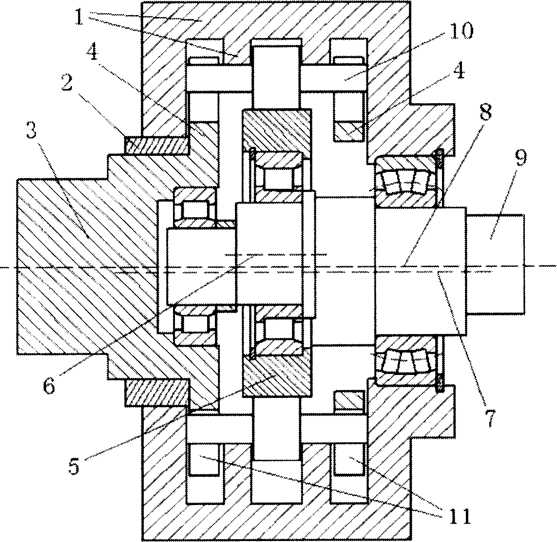
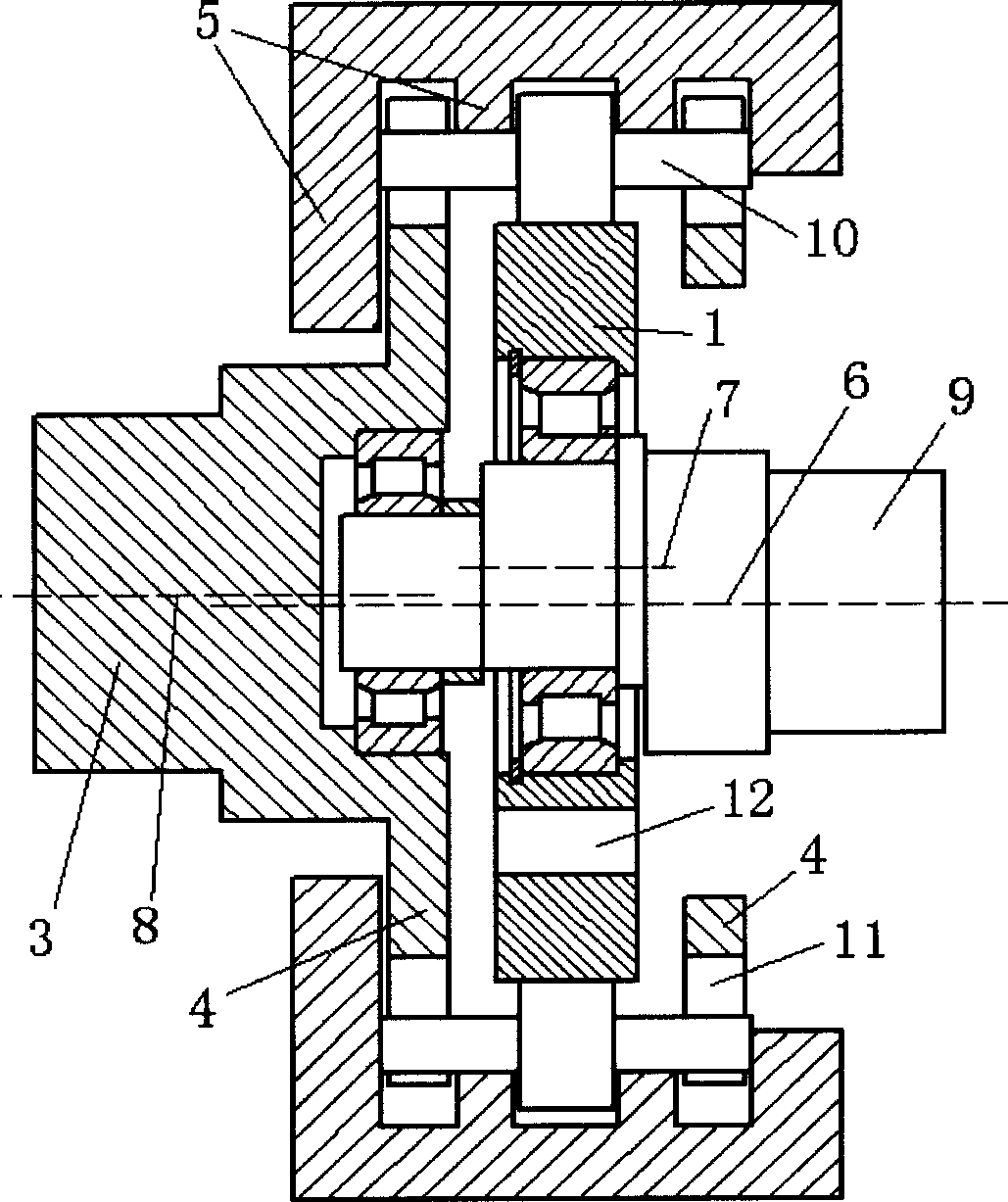
[0028] figure 1 , figure 2 The shapes and names of all the parts are based on the chapter "Moving tooth transmission" in Volume 3 of the fourth edition of "Machine Design Handbook" published by Chemical Industry Press and refer to the traditional national standard of cycloidal pinwheel transmission . It is particularly supplemented that, due to the eccentricity of the transmission parts in pairs, a fixed gear pin hole 12 for the installation of the W mechanism is added on the fixed gear.

[0029] Such as figure 1 As shown, for the convenience of description, it is assumed that the input shaft 9, the output shaft 3, and the rotation axis 8 of the force transmission plate (movable tooth revolution axis) are coaxial (the actual design can be handled flexibly), and the input shaft 9 and the output shaft 3 are installed on the base.

[0030] Obviously, figure 1 The ro...


PUM


Abstract

The invention relates to generalized cycloid oscillating tooth driving device. Its input and output shaft are parallel or concurrent. In the input-output shaft vertical plane, the ideal center projection of fixed gear, shock wave machine, and oscillating tooth ring is not concurrent each two. The revolution center of the oscillating tooth ring is at the connecting line of fixed gear and shock wave machine center. While the two rotation centers are concurrent, they will do circular motion at the same time. The invention can improve dynamic balance performance, production reliability, and technique, and reduce cost.

Description

technical field [0001] The present invention relates to a mechanical transmission device, which belongs to the expansion of a special case of the generalized double cosine movable tooth transmission already announced by the inventor, and particularly relates to a one-tooth difference movable tooth transmission device. Background technique [0002] At present, the known one-tooth difference planar movable tooth transmission generally adopts a double-row double-eccentric structure in order to achieve dynamic balance. reliability. Moreover, the double-row structure produces an additional moment to the machine base, which cannot be balanced. The above-mentioned problems also exist in the cycloidal pinwheel transmission and the involute gear planetary transmission with small tooth difference. [0003] In the Patent No. CN200410079279.3 "Arbitrary Tooth Difference Number Plane Movable Gear Transmission", when the number of teeth differences is g...

Claims


Application Information

Patent Timeline
IPC IPC(8): F16H1/32
Inventor 陈贤湘
Owner 陈贤湘
Learn More