Plasma treating coil

A plasma and coil technology, applied in the direction of plasma, discharge tube, electrical components, etc., can solve the problem of poor uniformity of edge plasma

Active Publication Date: 2006-10-25
BEIJING NAURA MICROELECTRONICS EQUIP CO LTD
View PDF1 Cites 3 Cited by
  • Summary
  • Abstract
  • Description
  • Claims
  • Application Information

AI Technical Summary

Problems solved by technology

Since the prior art uses a planar coil, its edge plasma uniformity is poor

Method used


Image

  • Plasma treating coil
  • Plasma treating coil
  • Plasma treating coil

Examples


Embodiment Construction

[0019] The following examples are used to illustrate the present invention, but are not intended to limit the scope of the present invention. Those of ordinary skill in the relevant technical field can also make various changes and modifications without departing from the spirit and scope of the present invention. Therefore All equivalent technical solutions also belong to the category of the present invention, and the scope of patent protection of the present invention should be defined by each claim.

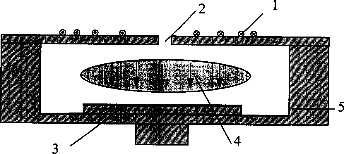
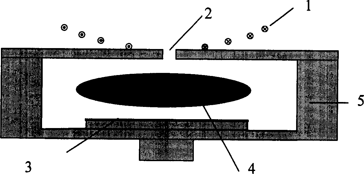
[0020] refer to image 3 , the plasma etching device coil of the present invention is a coil using a three-dimensional structure, and is installed on the upper cover of the reaction chamber 5 . Figure 4 This is the top view of the coil, the coil is composed of 4 turns, each turn is a circle with gaps in the same direction, these circles are on different planes, and the centers of these circles are all on the same axis, and finally connect each turn , the circle with larger d...


PUM


Abstract

This invention relates to plasma process circle coils mounted on the top cover of a reacting cavity, which are in a solid structure, the circles are placed on different planes and the centers of the circles are on a same axes, the larger of the diameter of a circle, the further away from the top cover of the reacting cavity is and notches are set on the same direction of the circles to form circle in-and-out ports, the outlet of a circle is connected with the inlet of the adjacent outer circle, the inlet of the most inside circle and the outlet of the most outside circle are taken as two lead ends of the plasma process coils to alter the distribution state of the electromagnetic field and increase the uniform distribution degree.

Description

technical field [0001] The invention relates to semiconductor processing equipment, in particular to a plasma processing coil of a semiconductor etching machine. Background technique [0002] In the manufacture of semiconductor devices, the different material layers on integrated circuits or flat panel displays are typically formed by chemical and physical deposition or etching. In a broad sense, etching technology includes the technology of uniformly removing the entire surface of the material, or selectively removing parts with patterns, and its types can be divided into wet etching and dry etching. Dry etching is an etching technique that uses gas discharge to generate plasma to remove thin films. Etching generally occurs in a reaction chamber in a plasma process system. The application of dry etching mainly requires attention to etch rate, etch uniformity and etch profile. Uniformity is an indicator of the difference in etching rate at different etching positions. Bet...

Claims


Application Information

Patent Timeline
Patent Type & Authority Applications(China)
IPC IPC(8): H01J37/32H01L21/205H01L21/3065H05H1/00
Inventor 王铮
Owner BEIJING NAURA MICROELECTRONICS EQUIP CO LTD
Why Eureka
Try Eureka