
Exhaust gas purification device

A technology of exhaust purification device and exhaust pipe, which is applied to exhaust device, muffler device, transportation and packaging, etc., can solve the problem of overheating of secondary air supply pipe, and achieve the effect of preventing overheating.

Active Publication Date: 2006-11-01
YAMAHA MOTOR CO LTD
View PDF1 Cites 1 Cited by
  • Summary
  • Abstract
  • Description
  • Claims
  • Application Information

AI Technical Summary

Problems solved by technology

[0005] However, for such an exhaust purification device in which the secondary air supply pipe is introduced into the muffler, when the high-temperature exhaust gas discharged from the end of the exhaust pipe is directly sprayed to the secondary air supply pipe, the secondary air supply pipe is overheated

Method used


Image

  • Exhaust gas purification device
  • Exhaust gas purification device
  • Exhaust gas purification device

Examples


Embodiment Construction

[0029] An embodiment of the present invention will be described below with reference to the drawings.

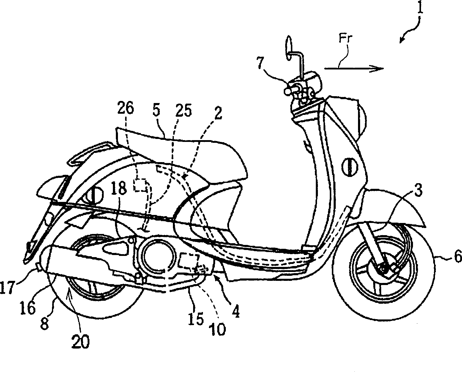
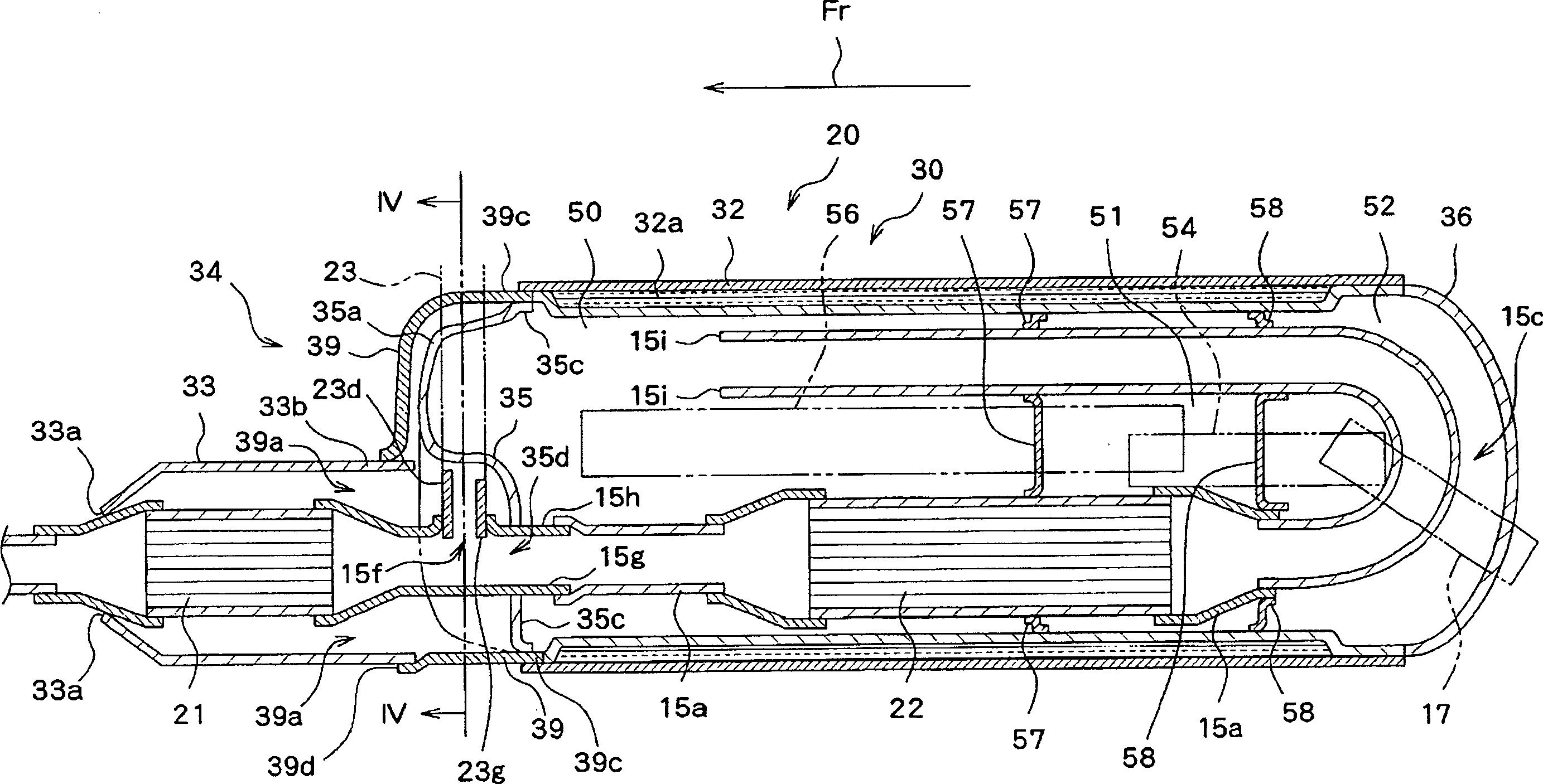
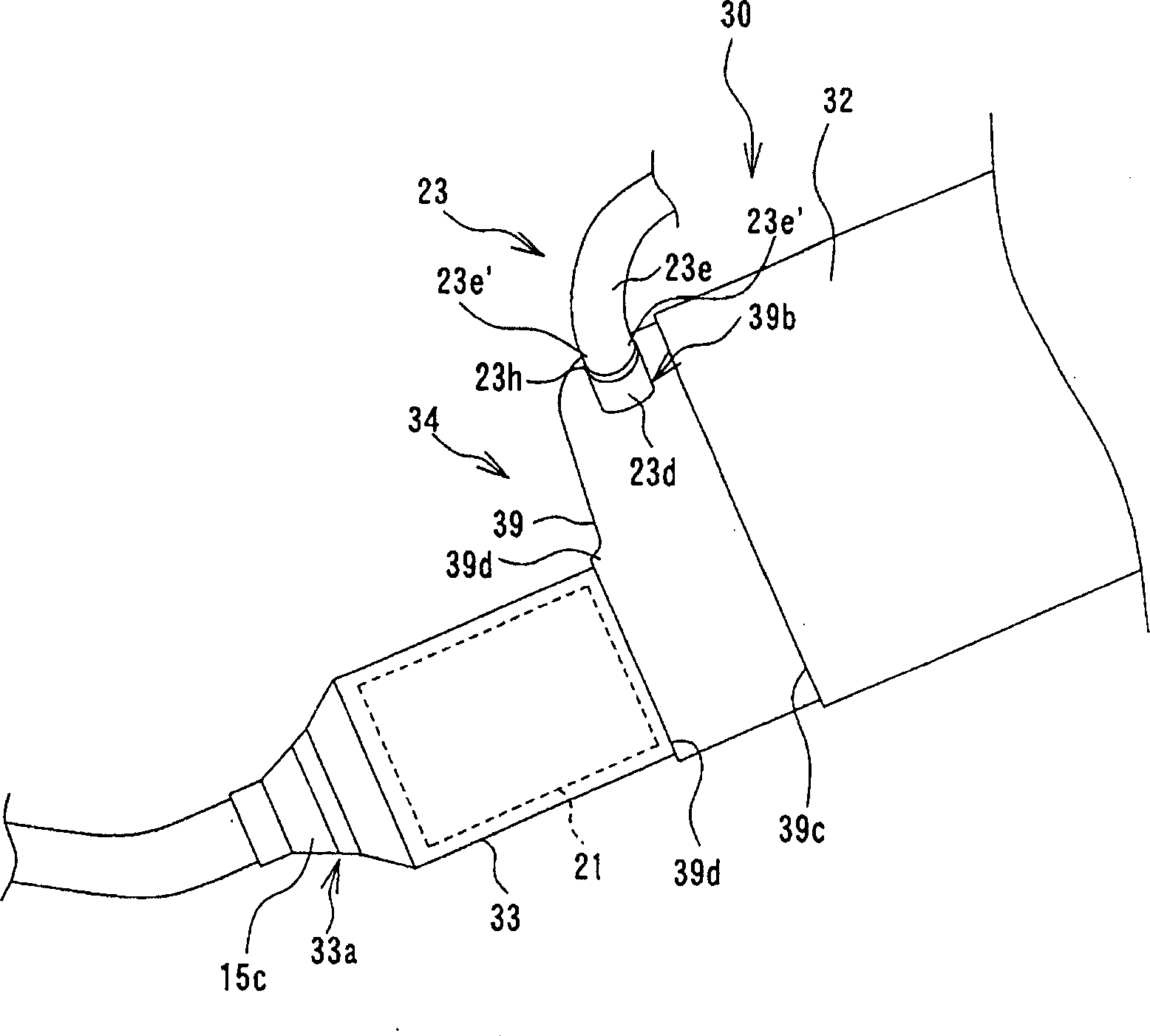
[0030] Figures 1 to 4 An exhaust purification device according to a first embodiment of the present invention is shown. figure 1 is a side view of the outline of a motorcycle configured as a saddle-riding vehicle according to the present invention, figure 2 is a sectional view of the exhaust purification device 20 according to the first embodiment, image 3 is a perspective view of the front portion of the exhaust purification device 20 in the direction of travel of the vehicle. Figure 4 is along figure 2Cross-sectional view on line IV-IV.

[0031] exist figure 1 Among them, the front end of an underbone frame 2 of a motorcycle 1 supports a front fork 3 so that the front fork can turn left and right. The central portion of the vehicle frame 2 supports a unit swing engine unit 4 so that the unit swing can be vertically (up and down). The vehicle seat 5 is installed...


PUM


Abstract

The present invention discloses an exhaust gas purifying apparatus which is capable of preventing the high temperature discharge from heating the secondary air supply pipe and restraining the oxide quantity flowing into the discharge pipe from reducing. The exhaust gas purifying apparatus comprises an exhaust pipe connectable to an engine, a upstream and lower reach catalyst arranged in the exhaust pipe, a secondary air supply pipe connected to the exhaust pipe on an upstream side of a position, in which the catalyst is arranged, and a muffler that accommodates an end of the exhaust pipe, through which exhaust gases are discharged, and a connection between the secondary air supply pipe and the exhaust pipe, wherein the muffler is further constructed such that the exhaust gases discharged from said end of the exhaust pipe are prevented from being jetted directly toward the secondary air supply pipe.

Description

technical field [0001] The present invention relates to an exhaust purification device in which exhaust gas discharged from an engine is mixed with secondary air to be purified. Background technique [0002] Generally, a motorcycle is provided with an exhaust purification device in which a catalyst is provided in an exhaust pipe connected to the engine, and a secondary air supply pipe is connected to the upstream end of the catalyst to allow the secondary air It is mixed with the exhaust gas to activate the catalyst (for example, Patent Document 1). However, with the conventional exhaust purification device, the connection portion of the exhaust pipe and the secondary air supply pipe is exposed to the outside. Therefore, there is a fear that the coating coating on the connection portion will deteriorate due to the heat of the exhaust gas flowing through the exhaust pipe, thereby spoiling the appearance. [0003] Therefore, it is conceivable to conceive an exhaust gas purif...

Claims


Application Information

Patent Timeline
Patent Type & Authority Applications(China)
IPC IPC(8): F01N3/30B01D53/86B01D53/94B62M7/02B62M7/08F01N1/08F01N3/24F01N13/08
Inventor 西村英浩泷井修金田勇治远藤道彦
Owner YAMAHA MOTOR CO LTD
Learn More