Optical lens, light emitting device package using the optical lens, and backlight unit

A technology of optical lenses and light-emitting devices, applied in the field of optical lenses, can solve the problems of increased display panels, complicated assembly process, incorrect arrangement, etc.

Inactive Publication Date: 2006-11-01
LG ELECTRONICS INC +1
View PDF2 Cites 42 Cited by
  • Summary
  • Abstract
  • Description
  • Claims
  • Application Information

AI Technical Summary

Problems solved by technology

[0019] The disadvantage of the backlight unit 90 constituted in this way is that a plurality of LED assemblies 90 should be installed with a hot spot baffle 80 called a diverter thereon, which complicates the assembly process.
[0020] Another disadvantage is that if the hot s...

Method used


Image

  • Optical lens, light emitting device package using the optical lens, and backlight unit
  • Optical lens, light emitting device package using the optical lens, and backlight unit
  • Optical lens, light emitting device package using the optical lens, and backlight unit

Examples


Embodiment Construction

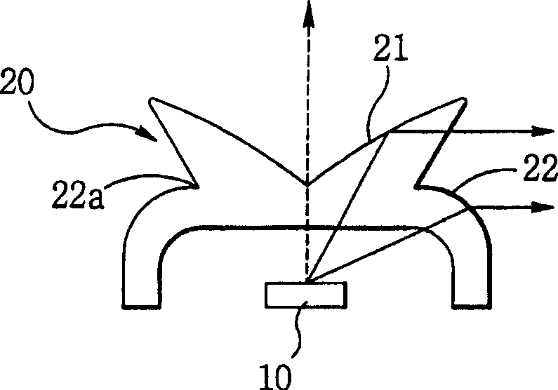
[0044] See Figure 7 , The optical lens 200 according to the first embodiment of the present invention includes: a reflective surface 210 formed thereon for reflecting light emitted upward from the light emitting device; and a bottom refraction surface 220 for refracting light emitted upward from the light emitting device And allow the light to reach the reflective surface 210, wherein the path of the light incident from below is changed to reach the side of the optical lens 200.

[0045] Meanwhile, the optical lens 200 includes a body. The body has a reflective surface 210 formed thereon, and is also formed with a bottom refraction surface 220 from which light incident thereunder is refracted and emitted.

[0046]The light incident on the reflective surface 210 is emitted from the bottom of the main body to the upper part of the main body, and the light incident from the bottom of the main body is composed of light refracted and emitted above the main body and light emitted to th...


PUM


Abstract

An optical lens, a light emitting device package using the optical lens and a backlight unit are disclosed, whereby light irradiated upward of a light emitting device is refracted from a bottom refraction surface to allow reaching a reflection surface, and an optical lens is mounted for reflecting the light sideways of the lens from the reflection surface to minimize an amount of light irradiated upward of the lens while increasing the amount of light irradiated toward the lateral surface of the lens, thereby limiting the generation of a hot spot to the maximum. The present invention dispenses with a hot spot baffle plate and a complicated assembly process to enable to reduce the number of parts and to decrease the thickness of a panel.

Description

[0001] This application claims the rights of Korean application No. 10-2005-0034473 filed on April 26, 2005 and Korean application No. 10-2005-0034543 filed on April 26, 2005, and these two applications are cited here as reference. Technical field [0002] This specification relates to an optical lens, a light emitting device assembly using the optical lens, and a backlight unit. Background technique [0003] The conventional light emitting diode is optically configured with a domed lens, and light is restricted to be distributed in a predetermined area relative to the central optical axis. If a liquid crystal display (LCD) backlight unit is made of such a light-emitting diode, a potential problem is that due to the light-emitting characteristics of the light-emitting diode, uniform light characteristics cannot be obtained. [0004] This indicates that a sufficient distance is required to uniformly mix the white light emitted from the light emitting diode, making it difficult to o...

Claims


Application Information

Patent Timeline
IPC IPC(8): G02B3/00H01L33/58G02F1/1335
CPCG02B19/0028G02B19/0061G02B19/0071G02F1/133603G02F1/133606G02F1/133607H01L33/58
Inventor 张峻豪徐廷勋
Owner LG ELECTRONICS INC
Why Eureka
Try Eureka