
Exposure apparatus

A technology for exposure devices and lasers, which is applied in printing devices, optics, using apertures/collimators, etc., and can solve problems such as loss of real-time performance

Inactive Publication Date: 2006-11-01
FUJIFILM CORP
View PDF1 Cites 0 Cited by
  • Summary
  • Abstract
  • Description
  • Claims
  • Application Information

AI Technical Summary

Problems solved by technology

This is to monitor the light quantity of LD102 in real time based on the purpose of stabilizing the beam light quantity, but at this time there is astigmatism that is not detected by the photosensitive surface of the sensor 118, so the relationship between the light quantity of the image surface and the photosensitive quantity of the sensor 118 deviates from the linear relationship and loses real-time sex

Method used


Image

  • Exposure apparatus
  • Exposure apparatus
  • Exposure apparatus

Examples


Embodiment Construction

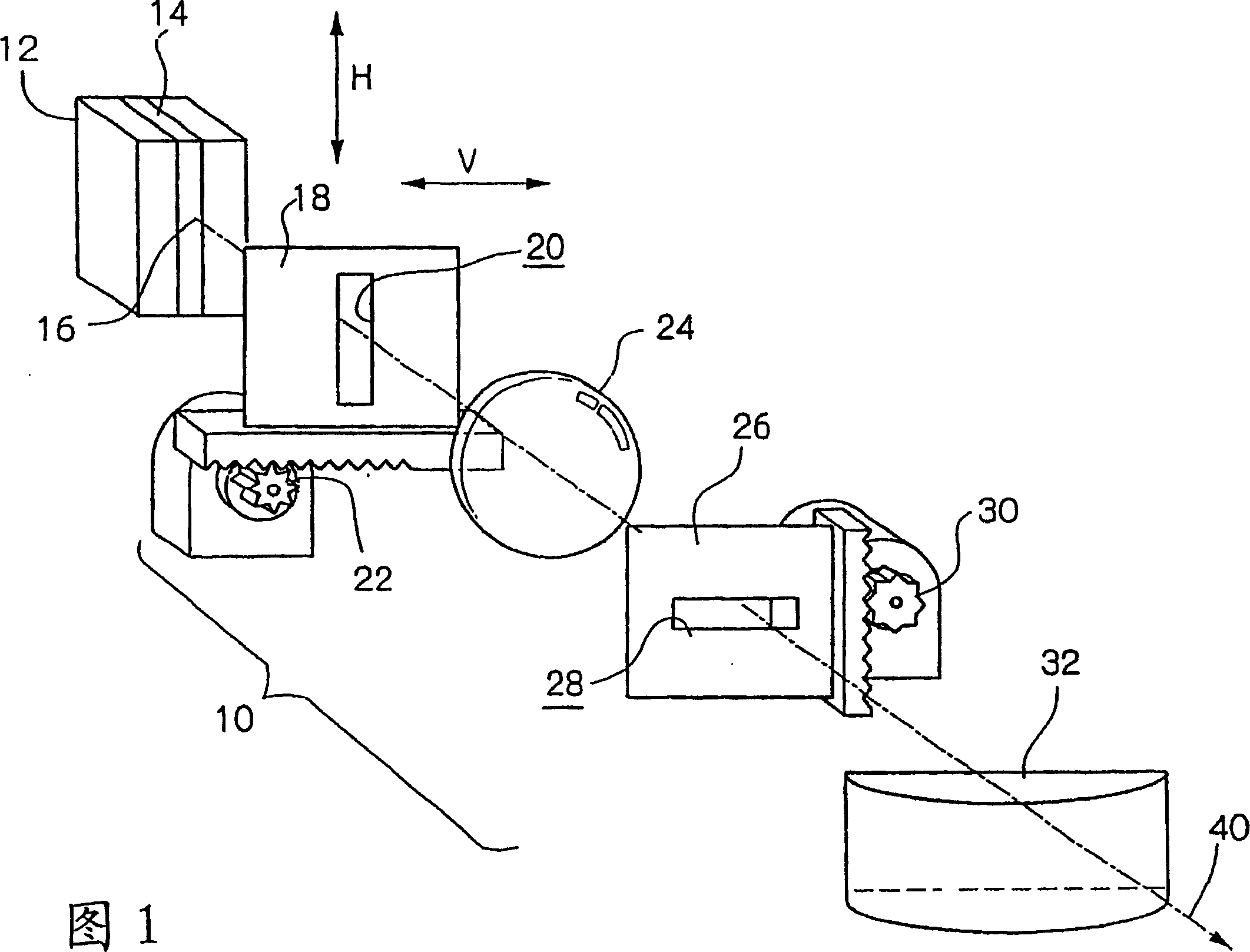
[0033] FIG. 1 is a perspective view showing an exposure apparatus according to a first embodiment.

[0034] As shown in FIG. 1 , the exposure apparatus 10 first restricts the light beam 40 emitted from the light emitting point 16 of the laser diode (hereinafter referred to as LD) 12 by the first slit 20 provided in the first slit plate 18 . At this time, the first slit 20 confines the light beam in a direction (arrow V) perpendicular to the active layer 14 of the LD 12 and has a moving mechanism 22 for moving the first slit plate 18 in the arrow V direction. As shown in FIG. 1, this moving mechanism 22 may be formed by providing a long hole in the arrow V direction as a simpler mechanism in addition to a mechanism composed of a driving device that combines a stepping motor with a rack and pinion, so that The mechanism that the first slit plate 18 can move in the arrow V direction along the long hole and is fixed in place with screws. At this time, if the scale is engraved on ...


PUM


Abstract

The invention provides an exposure device. In this exposure device, a GaN series blue semiconductor laser is used as a light source, and it is characterized in that: the aperture number of the coupling lens closest to the light emitting surface of the active layer of the blue semiconductor laser is set as NA, and When the beam spread angle from the light emitting surface is α, NA·tan(α / 2)≦2.0 is satisfied.

Description

[0001] This application is filed in accordance with Article 42 of the Implementing Rules of the Patent Law, and is a divisional application of the Chinese patent application with the application number 200410008889.4 filed on March 25, 2004 entitled "Exposure Device". technical field [0002] The present invention relates to an exposure device. Background technique [0003] In the past, in semiconductor lasers that emit light in the long-wavelength red to infrared region, a beam confinement device (aperture) was installed after a coupling lens that converts the beam emitted from a laser crystal into approximately parallel light or converging light, or a coupling lens was used. The aperture is used to confine the beam and perform beam shaping. [0004] In GaN-series semiconductor lasers emitting blue light that have come into practical use in recent years, materials that do not absorb blue light, such as sapphire or SiC (silicon carbide), are used as substrates. [0005] The...

Claims


Application Information

Patent Timeline
Patent Type & Authority Applications(China)
IPC IPC(8): G03B27/00G21K1/02
CPCG21K1/02
Inventor 早川利郎松本研司森本美范齐藤贤一
Owner FUJIFILM CORP
Features
  • Generate Ideas
  • Intellectual Property
  • Life Sciences
  • Materials
  • Tech Scout
  • Unparalleled Data Quality
  • Higher Quality Content
  • 60% Fewer Hallucinations
Learn More