
Method for forming a laser beam and laser processing method

A laser processing method and laser beam technology, applied in the field of laser processing, can solve problems such as quality reduction, achieve the effects of simple structure, reduce beam cross-section, and avoid mechanical rotation

Inactive Publication Date: 2006-11-08
HITACHI SEIKO LTD
View PDF0 Cites 6 Cited by
  • Summary
  • Abstract
  • Description
  • Claims
  • Application Information

AI Technical Summary

Problems solved by technology

This ultimately results in a reduced quality of the drilled holes compared to that obtained with an ideally shaped laser beam

Method used


Image

  • Method for forming a laser beam and laser processing method
  • Method for forming a laser beam and laser processing method
  • Method for forming a laser beam and laser processing method

Examples


Embodiment Construction

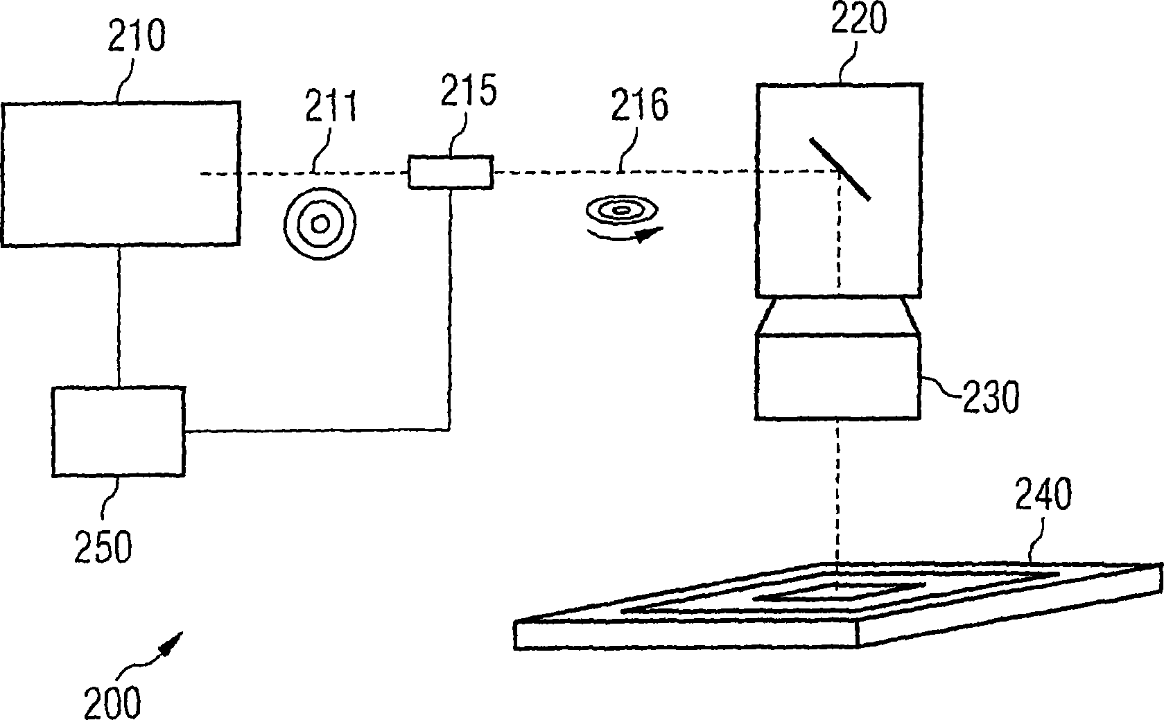
[0024] attached figure 2 The laser processing device 200 represented in includes a laser light source 210 emitting a first laser beam 211 . According to the embodiment shown here, the first laser beam 211 - which is a pulsed laser beam - has a transverse beam profile which can be well approximated by a Gaussian intensity distribution. The first laser beam 211 is incident on the beam shaping element 215 , and the beam shaping element 215 converts the transverse intensity distribution of the first laser beam 211 into a changed transverse intensity distribution of the second laser beam 216 . The intensity distribution of the second laser beam 216 is asymmetric such that the intensity distribution of the second laser beam 216 has a preferential position perpendicular to the optical axis of the second laser beam 216 . The beam shaping element 215 is connected to a controller 250 by which the beam shaping element 215 can be controlled such that the preferential direction of the int...


PUM


Abstract

The invention relates to a method for forming a laser beam, wherein a first laser beam (211) having a first transverse intensity distribution is directed onto a beam forming element (215) and the first laser beam is converted to a second laser beam (216) having a second transverse intensity distribution by means of the beam forming element. According to the invention, the second intensity distribution has a preferred direction perpendicular to the optical axis of the second laser beam and the beam forming element is operated in such a manner that the preferred direction rotates about the optical axis. The beam forming element can be an optical element which rotates about the optical axis of the first laser beam by virtue of a mechanical movement. Preferably, the beam forming element is configured by a dynamic system which, when actuated accordingly and while avoiding any mechanical rotation, allows to produce virtually any beam width of the second laser beam having any intensity distribution. The invention also relates to a laser processing method which is characterized by using the method for forming a laser beam for the laser processing of material.

Description

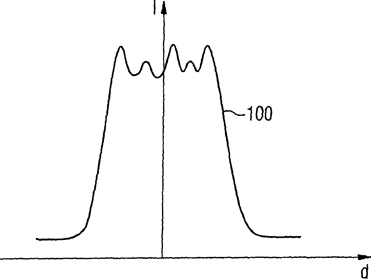
technical field [0001] The invention relates to a method for shaping a laser beam, wherein the transverse intensity distribution of the laser beam is changed by means of a beam shaping element. Furthermore, the present invention also relates to a laser treatment method using the above method. Background technique [0002] When drilling circuit boards in the field of electronic equipment manufacturing, the shape of the drilled holes is an important factor for the quality of electronic components formed on the circuit board. By supplying increasing laser power, holes can be drilled simultaneously for different circuit board materials by so-called punching. This is considered to drill a hole where material ablation is achieved by laser beam pulses incident on the same location. In order to drill a hole when punching - punching a hole with a larger hole diameter compared to the minimum focus diameter, the focus width of the laser beam cannot simply be increased, as this would ...

Claims


Application Information

Patent Timeline
IPC IPC(8): B23K26/073B23K26/06B23K26/38
CPCB23K26/0648B23K26/064B23K26/0643B23K26/382B23K2101/42
Inventor 汉斯·J·梅尔乌韦·梅特卡
Owner HITACHI SEIKO LTD
Learn More