
Production process of building vacuum glass plate

A technology of vacuum glass plate and production method, which is applied in glass forming, glass re-forming, glass manufacturing equipment and other directions, can solve the problems of low pumping rate, difficult to achieve vacuum degree, and many operation links, etc., and improve the overall strength. and stiffness, enhanced wind pressure resistance, and simple production process.

Inactive Publication Date: 2006-11-15
王世忠
View PDF7 Cites 21 Cited by
  • Summary
  • Abstract
  • Description
  • Claims
  • Application Information

AI Technical Summary

Problems solved by technology

Its main disadvantages are as follows: (1) The process of preparing the air extraction hole and installing the air extraction port on the glass plate is complicated, and because the air extraction port is very thin, the air extraction rate is small, the production efficiency is low, and the space formed by the two pieces of glass is not easy to reach a higher level. The degree of vacuum, thereby reducing the heat insulation and sound insulation effect of vacuum glass
At the same time, the final sealing and protection of the air suction port is a difficult problem in technology. Although there are many patents, such as CN 03263112. (2) evenly and reliably placing and fixing a large number of ceramic pillars and metal wires with a diameter less than 1 mm on the glass plate is very troublesome, difficult and time-consuming work in industrial production, and Resulting in low yield; (3) The production process of the above-mentioned vacuum glass is complex, with many operating links and low yield, so it is difficult to realize large-scale, low-cost industrial production

Method used


Image

  • Production process of building vacuum glass plate

Examples


example 1

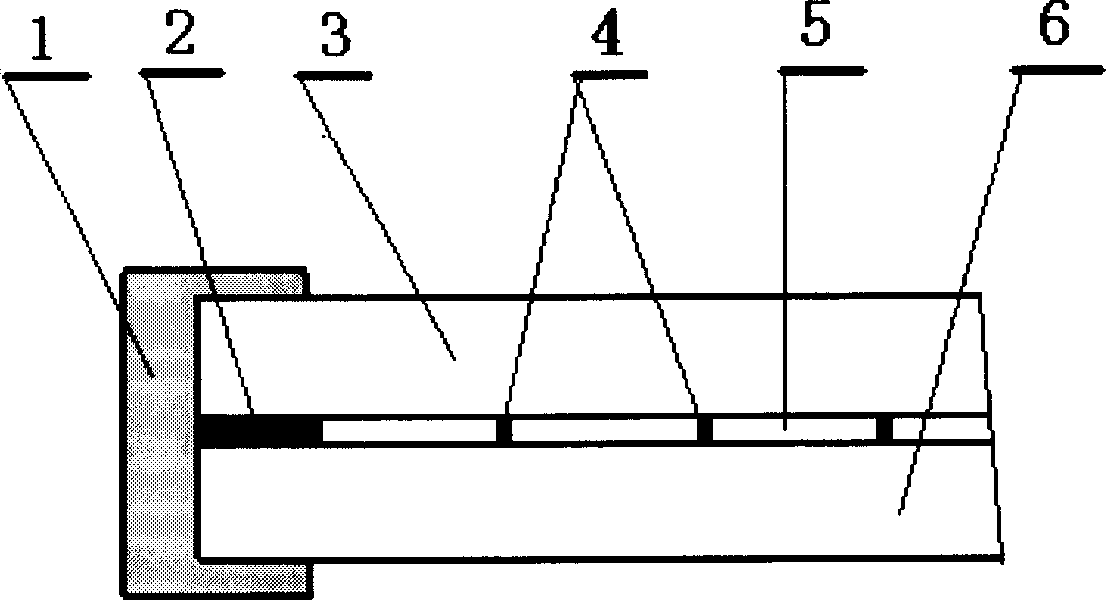
[0009] Example 1. Cut the purchased ordinary float glass with a thickness of 3mm and the Low-E glass with online coating to the required size, such as a rough board of 1000mm×600mm, and process it with an edger and a cleaning and drying machine Finally, it is sent to the screen printing process with clean environment; use a screen printing machine to print the pattern of the peripheral welding strip and the supporting welding point in the middle area on the frosted glass. The printing ink is prepared from solder glass powder and scraper oil. The printed peripheral welding width is 8mm, the diameter of the supporting welding spot in the middle area is 0.5mm, the interval is 25mm, and the thickness is 0.32mm. After being heated and dried by the dryer, it is sent to the purification studio for lamination operation; the float glass with the printed pattern is placed on a special fixture car, and the processed Low-E glass is laminated and fixed. Position, there is a certain gap bet...

example 2

[0010] Example 2. Order or process the required specifications, such as toughened glass with an overall size of 3m×2m and a thickness of 15mm. The purchased Low-E glass with a thickness of 5mm and online coating is cut into the same specification and size, and processed by an edging machine and a cleaning and drying machine; use a screen printing machine to print peripheral welding strips on the tempered glass, And the middle area supports the pattern of solder joints, and the printing ink is prepared from solder glass powder, scraper oil, etc. The printed welding width is 15mm, the diameter of the supporting welding spot in the middle area is 2mm, the interval is 50mm, and the thickness is 0.32mm. After being heated and dried by the dryer, it is sent to the purification studio for assembling operation; the tempered glass with printed pattern is placed on a special fixture car, and the processed Low-E glass is stacked on it, and the position is fixed. There is a certain gap b...


PUM


Abstract

A process for preparing vacuum glass plate for building features that the silk screen print is used to print peripheral sealing band and the welding glass material on internal supporting dots, and the glass sealing and the generation of vacuum cavity is performed by high-temp vacuum sealing.

Description

Technical field [0001] The invention relates to an industrialized production method of vacuum glass with a new structure, in particular to an industrialized production method of a building vacuum glass plate with good thermal insulation, sound insulation performance and wind pressure resistance for buildings. Background technique [0002] Architectural vacuum glass with a vacuum cavity has good thermal insulation properties. The use of building vacuum glass is an important way to reduce the heat loss of the building envelope and ensure building energy saving. [0003] For more than ten years, the demand for energy saving and sound insulation in buildings has promoted the development of vacuum glass production technology for doors and windows. Especially since PCT / AU94 / 00305 (CN 94192667.2) and PCT / AU1995 / 000640 (CN 9519665.1) were disclosed, there have been dozens of utility models and invention patents in this respect. However, because these utility models and inventions ...

Claims


Application Information

Patent Timeline
Patent Type & Authority Applications(China)
IPC IPC(8): C03B23/203
Inventor 王世忠
Owner 王世忠
Learn More