Bucket screw centrifugal vane of fan and application method of said vane in fluid delivering thereof

A technology of centrifugal impeller and bucket screw, which is applied to the centrifugal impeller of turbofan bucket screw and the application field of the impeller in fluid transportation, and can solve the problems of advanced design of impeller without substantial breakthrough, need of diffuser reflux device, insufficient improvement, etc.

Inactive Publication Date: 2006-11-15
QINHUANGDAO SONGHE COMPOSITE MATERIALS DEV
View PDF2 Cites 8 Cited by
  • Summary
  • Abstract
  • Description
  • Claims
  • Application Information

AI Technical Summary

Problems solved by technology

The disadvantage is that due to the characteristics of the centrifugal impeller structure, the fluid relay transmission between the two centrifugal impellers has a direction turn, which requires a diffuser, a bend, and a reflux device, which has energy loss
The designs that highlight the invention p

Method used


Image

  • Bucket screw centrifugal vane of fan and application method of said vane in fluid delivering thereof
  • Bucket screw centrifugal vane of fan and application method of said vane in fluid delivering thereof
  • Bucket screw centrifugal vane of fan and application method of said vane in fluid delivering thereof

Examples


Embodiment Construction

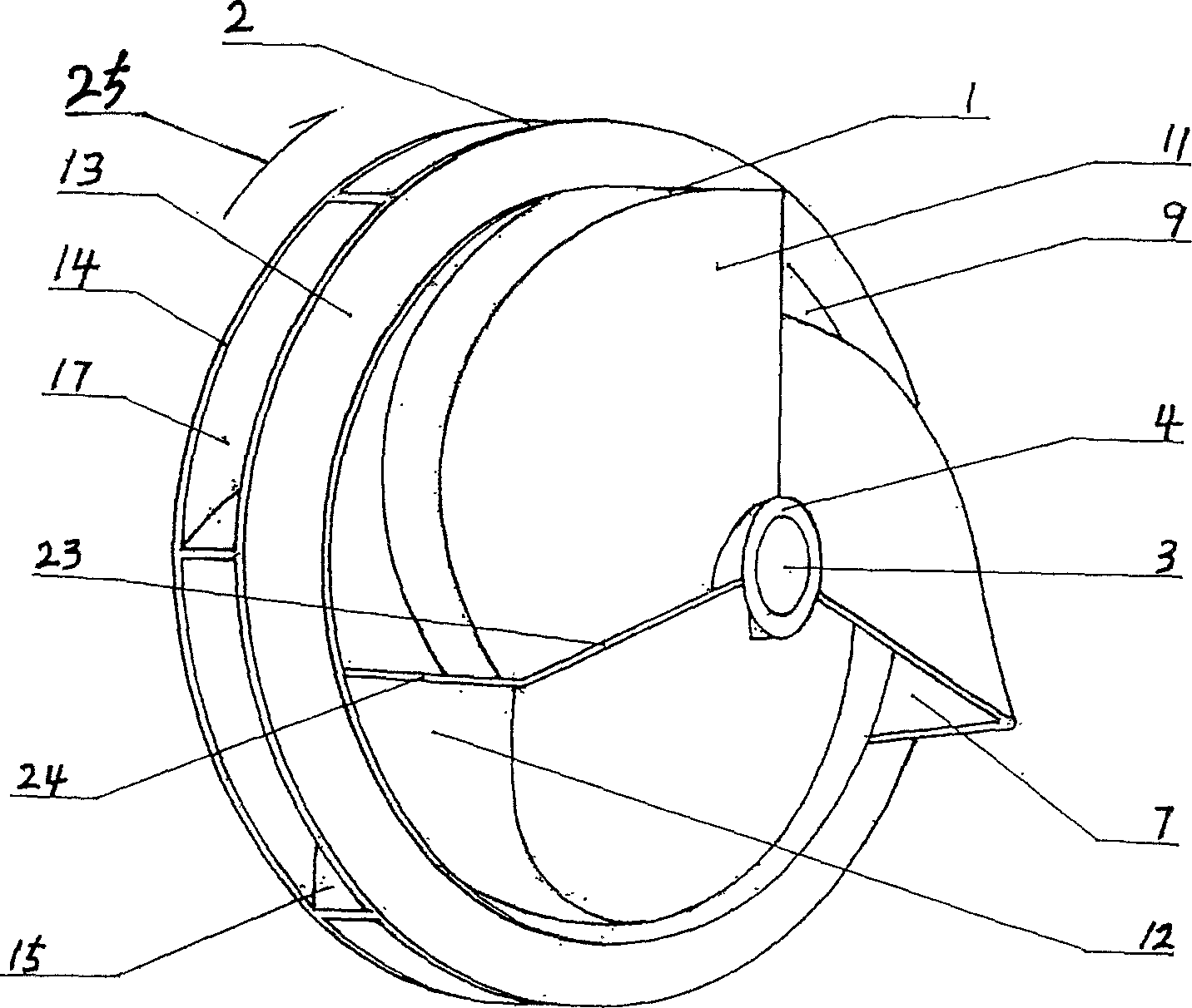
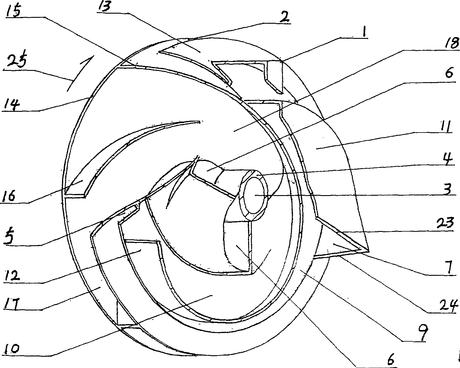
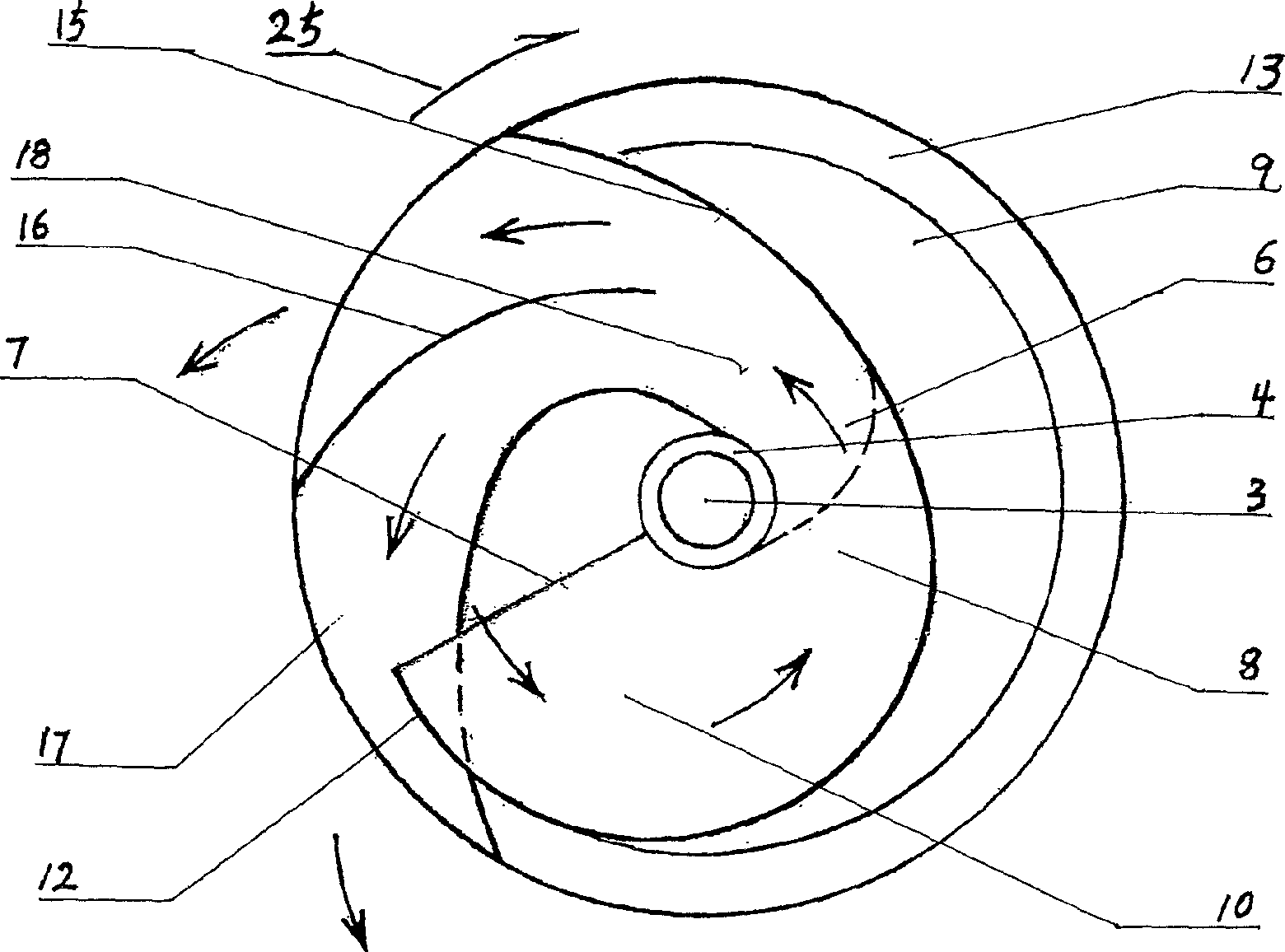
[0037] In order to understand the above-mentioned features and advantages of the present invention more clearly, the present invention will be further described in detail below in conjunction with the accompanying drawings and specific application examples.

[0038] In the embodiment, there are three main channels and a turbofan bucket spiral centrifugal impeller with an isolation sealing groove.

[0039]The turbofan bucket spiral centrifugal impeller consists of the impeller as a whole; the front and rear stages are each in the shape of a flat cylinder in the axial direction, and the center of the axial circular surface; the power shaft hole and hub that run through the central axis of the front and rear two stages, and the front stage turbofan bucket The impeller: three axial turbofan blades uniformly arranged on the outer peripheral surface of the hub at constant intervals and three radial scroll blades uniformly arranged on the axial peripheral surface of the rear disc with...


PUM


Abstract

The invention comprises integrated axial front and back stages. The front stage fan bucket impeller has a bucket-shape forward bended rectangular main runner screw-coiling round the hub. The back stage helical centrifugal impeller has a main centrifugal runner and a branch backward bended rectangular centrifugal runner. The forward bended runner of the front stage is in communication with the backward bended runner of the back stage to form an integrated impeller.

Description

Technical field: [0001] The present invention relates to a fluid conveying equipment and the application method of the equipment in fluid conveying, in particular to the design scheme of the core working component impeller applied on the impeller type fluid conveying machinery, more specifically, the turbofan bucket of the present invention The spiral centrifugal impeller is applied to the vane type fluid conveying machinery. The impeller is driven by the prime mover to rotate and work, and energy is input to the fluid to accelerate the pressure of the fluid and drive the fluid to flow, so as to achieve the function of conveying the fluid. Background technique: [0002] At present, the single fan impeller or propeller impeller used in the blade type fluid conveying equipment and the axial flow fluid conveying machinery operates as the axial front sucks the fluid through the curved surface of the impeller blade, accelerates and pressurizes, and then outputs it axially. . The...

Claims


Application Information

Patent Timeline
IPC IPC(8): F04D29/24F04D29/30
Inventor 刘希文
Owner QINHUANGDAO SONGHE COMPOSITE MATERIALS DEV
Why Eureka
Try Eureka