

Substrate checking device
A substrate inspection, substrate technology, applied in the direction of measuring devices, transportation and packaging, instruments, etc., can solve the problems of insufficient light, complex structure of the device, obstruction of illumination light, etc., and achieve the effect of high-precision inspection
- Summary
- Abstract
- Description
- Claims
- Application Information
AI Technical Summary
Problems solved by technology
Method used
Image

Examples
no. 1 approach
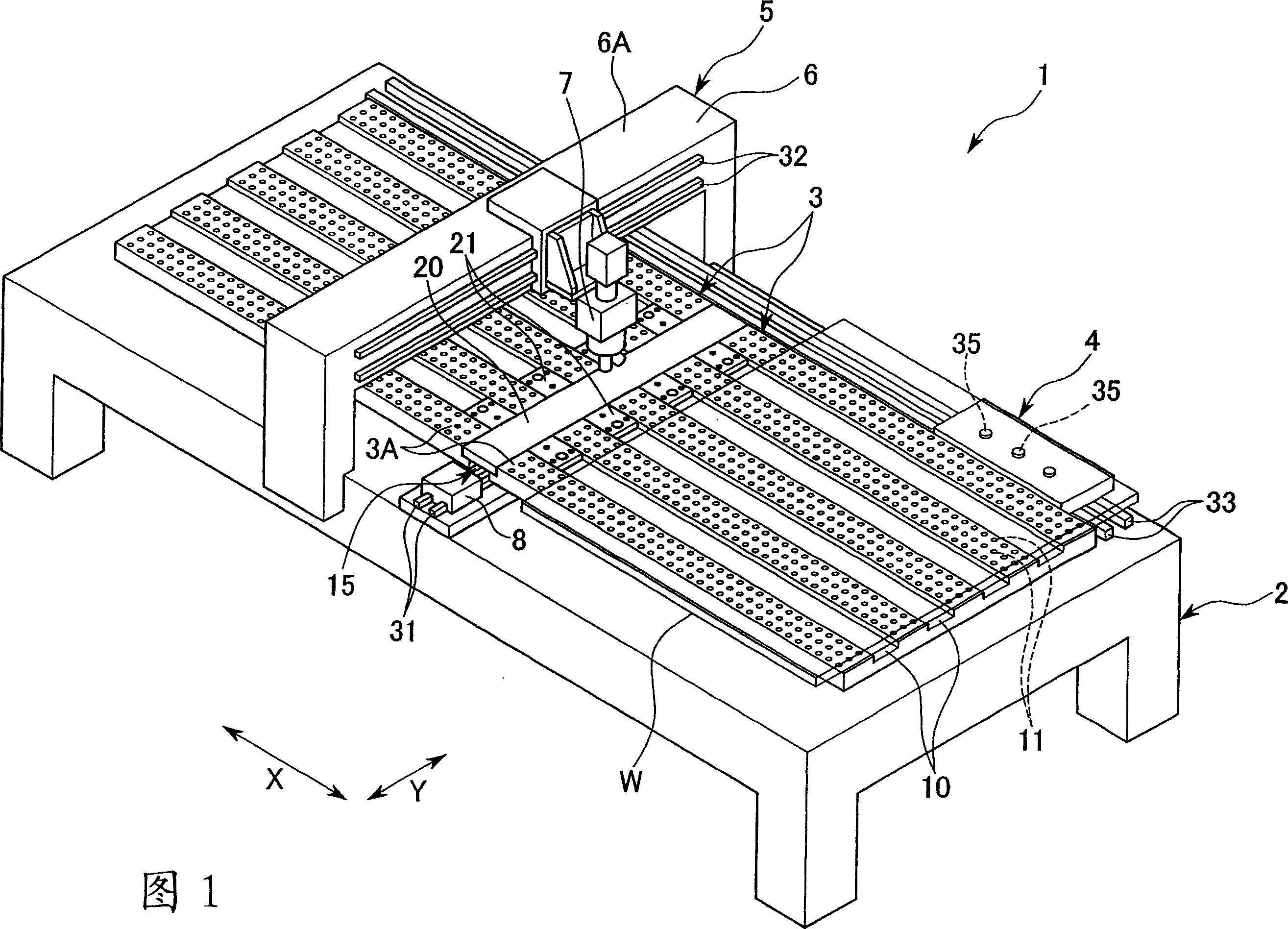
[0021] As shown in FIG. 1 , the substrate inspection apparatus 1 has a base unit 2 , and a floating table 3 and a transport unit 4 for transporting a glass substrate W along the floating table 3 are disposed on the upper portion of the base unit 2 . In FIG. 1, the conveyance part 4 is laid on the upper surface of the base part 2, and is provided so that it can move along the guide rail 33 extended in the X direction. A plurality of suction pads 35 for suction-holding the glass substrate W by coming into contact with the outer edge of the glass substrate W from below are also provided on the conveyance unit 4 . The conveying unit 4 sucks and holds the outer edge of the glass substrate W suspended on the levitation table 3 by means of the suction plate 35, and forcibly conveys the glass substrate W in the conveying direction from the near side of the levitation table 3. The direction in which one end faces the other end (hereinafter referred to as the X direction). Moreover, th...
no. 2 approach
[0036] The difference between the second embodiment of the present invention and the first embodiment lies in that the fixing method of the diffusion plate is different. Therefore, descriptions overlapping with those of the first embodiment are omitted.
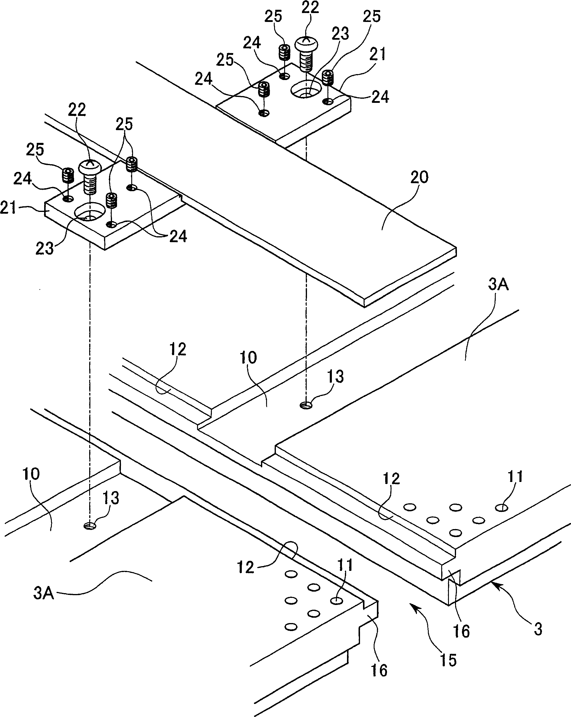
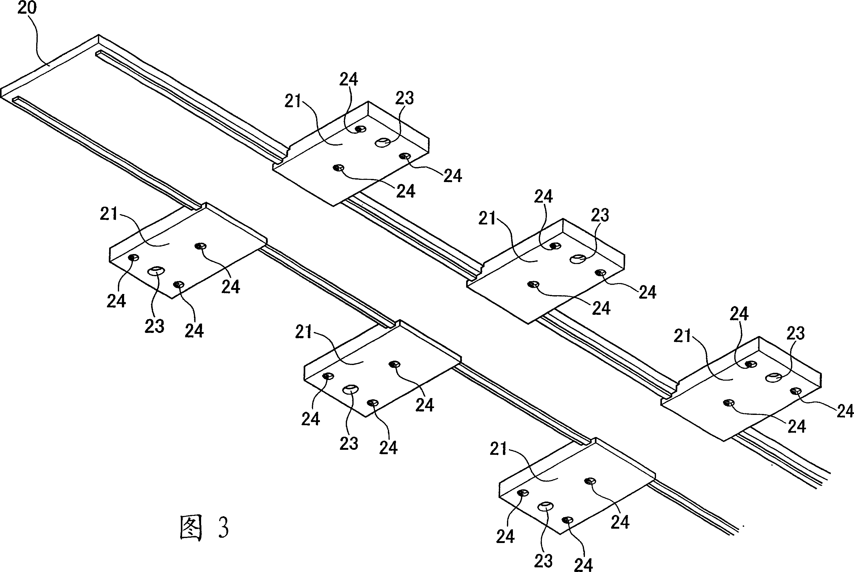
[0037] like Image 6 As shown, the fixing member 51 (fixing unit) holding the diffusion plate 20 is fixed to the outer edge of the rear surface of the diffusion plate 20 at the same interval as the concave portion 10 of the suspension table 3 . The outer shape of this fixing member 51 is the same as that of the fixing member 21 of the first embodiment.
[0038] When fixing the diffusion plate 20 , the spacer 52 is laid on the concave portion 10 of the levitation table 3 , and the fixing member 51 is inserted from above the spacer 52 in a nearly fitted state. A notch 52A is formed in the spacer 52 to avoid interference with the fastening member 22 . As the spacer 52 , various types of spacers having the same shape but diffe...
no. 3 approach
[0041] The third embodiment of the present invention differs from the first and second embodiments only in that the fixing method of the diffusion plate is different. Therefore, descriptions that overlap with those of the first and second embodiments are omitted.
[0042] As shown in FIG. 7 , in this embodiment, fixing means for fixing the diffusion plate 20 by air adsorption is provided on the levitation table 3 side. That is, a plurality of holes 61 penetrating in the vertical direction are formed in the support portion 16 of the levitation table 3 . Each hole 61 is connected to each connector 62 fixed below the support portion 16 , and each connector 62 is connected together by a pipe 63 . The piping 63 is connected to a vacuum pump not shown. In addition, a spacer 64 serving as an adjustment means and also as an adsorption part is disposed on the peripheral edge part of the upper opening of the hole 61 . A through hole communicating with the hole 61 is formed at the cen...
PUM
 Abstract
Description
Claims
Application Information