
Lower-pipe type permanent-magnet vortex heating device for oil well

A permanent magnet eddy current and heating device technology, which is applied in isolation devices, boreholes/well components, earthwork drilling and production, etc., can solve the problems of unsuitable oil well heating and difficulty in rotating motion, and achieve simple structure, high heat transfer efficiency, Good economical effect

Inactive Publication Date: 2006-11-22
INST OF ELECTRICAL ENG CHINESE ACAD OF SCI
View PDF1 Cites 1 Cited by
  • Summary
  • Abstract
  • Description
  • Claims
  • Application Information

AI Technical Summary

Problems solved by technology

In the current oil well production equipment, the external motor drives the sucker rod to do reciprocating linear motion through the transmission mechanism; and it is very difficult to realize the rotary motion in the oil pipe with limited space, so this heating device is not suitable for oil well heating

Method used


Image

  • Lower-pipe type permanent-magnet vortex heating device for oil well
  • Lower-pipe type permanent-magnet vortex heating device for oil well
  • Lower-pipe type permanent-magnet vortex heating device for oil well

Examples


Embodiment Construction

[0019] The present invention will be further described below in conjunction with specific embodiments and accompanying drawings.

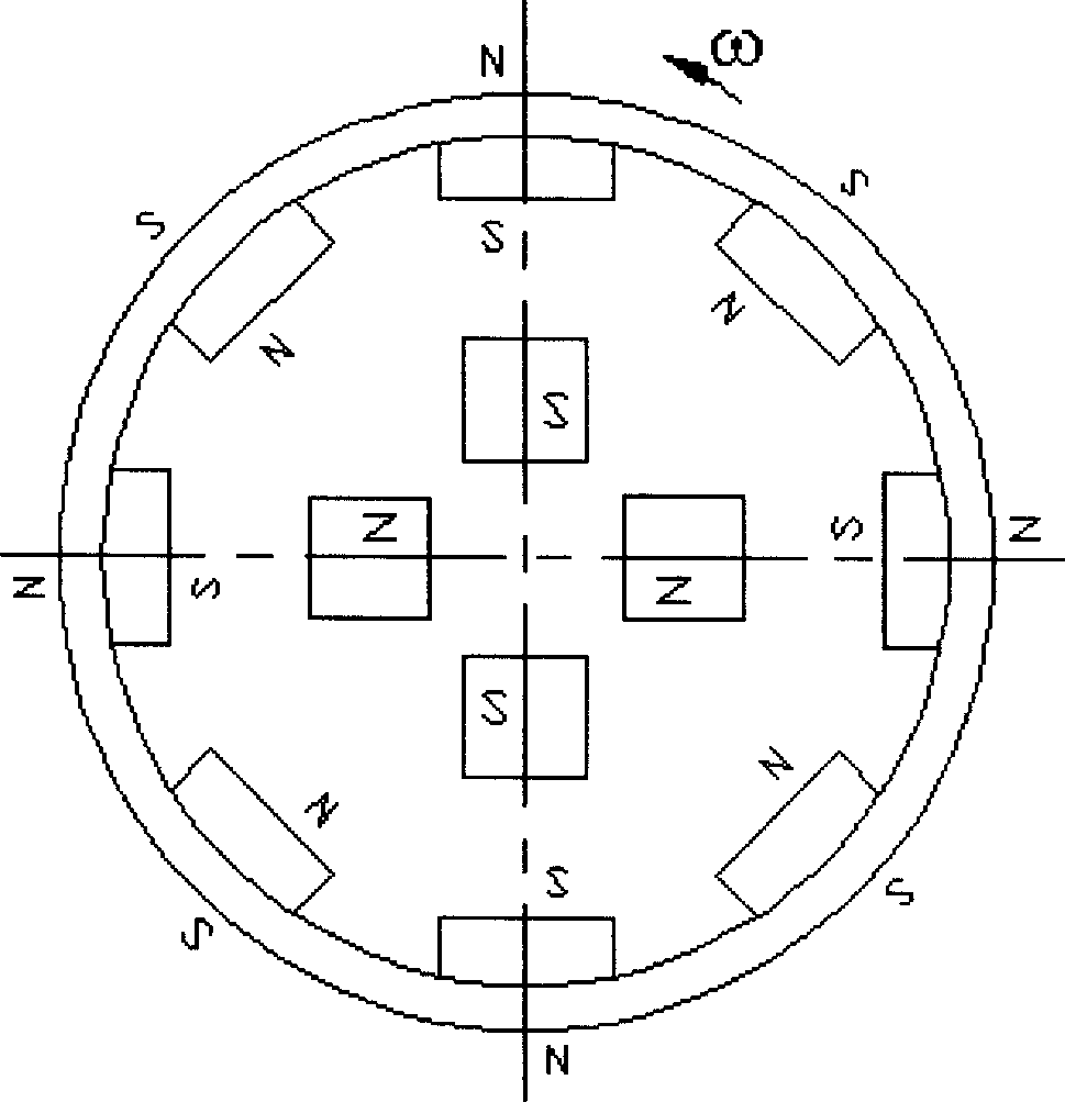
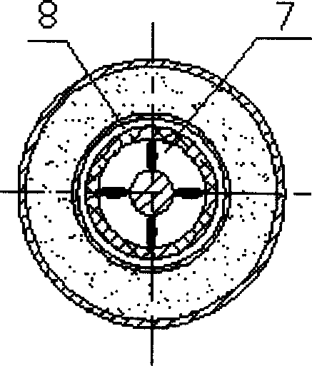
[0020] Fig. 2 is a schematic structural diagram of a specific embodiment of the present invention. As shown in Figure 2, the specific embodiment of the present invention consists of a sucker rod 1, an internal magnetic tubular permanent magnet 2, a bracket 3, an induction heating copper sleeve 4, a metal inner shell 5, a metal outer shell 6, and an internal flow passage 7 , Overcurrent outer channel 8 components. Wherein the sucker rod 1, the bracket 3, the induction heating copper sleeve 4, the overcurrent inner channel 7, and the overcurrent outer channel 8 are coaxially located in the magnetic hole of the inner magnetic tubular permanent magnet 2.

[0021] The sucker rod 1 is made of non-magnetic alloy steel with an outer diameter of 19 mm, and is arranged coaxially with the inner magnetic tubular permanent magnet 2 . The induction heating cop...


PUM


Abstract

The invention relates to a lower-in permanent magnetic vortex heater, which is formed by an internal-magnetic tubular permanent magnet (2), a magnetic non-conductive pumping rod (1), a sensitive heating copper muffle (4) that fixed with pumping rod (1) via magnetic non-conductive support (3), an overflow inner channel (7) and an overflow outer channel (8); the magnetic circuit is formed the internal-magnetic tubular permanent magnet (2) and the air gap inside the magnetic hole; the sensitive heating copper muffle (4) moves straight relative to the magnetic field whose axial direction is sine wave that generated by and internal-magnetic tubular permanent magnet (2), to generate vortex inside the tube wall; since the sensitive heating copper muffle (4) is between the overflow inner channel (7) and the overflow outer channel (8); when the overflow channel is filled with base oil, the sensitive heating copper muffle (4) is completely surrounded by base oil, and the sensitive vortex heat is completely transmitted to around base oil, to effectively keep temperature.

Description

technical field [0001] The invention relates to a device used for oil well heating, reducing crude oil viscosity and preventing wax deposition in oil production, in particular to a tube-type permanent magnet eddy current heating device for oil wells. technical background [0002] my country's domestic crude oil is characterized by high wax content, high freezing point, and high viscosity. During the production process, wax formation in oil wells, clogging of oil-producing layers and oil pipes generally occur, which seriously affects the stable and high production of oil wells. It is an important issue that needs to be solved. Japanese patent JP19670020242 discloses a pipeline heating device, which utilizes the AC skin effect to concentrate electric energy on the inner surface of a small-diameter carbon steel pipe and convert it into heat energy, and transfer the heat to the pipeline. The device was initially applied to the heating of fuel oil pipelines, and was later extende...

Claims


Application Information

Patent Timeline
IPC IPC(8): E21B36/00
Inventor 彭燕沙次文赵凌志李然宋述军许玉玉
Owner INST OF ELECTRICAL ENG CHINESE ACAD OF SCI
Learn More