Pipe hoop stress tensility testing method

A technique of hoop stretching, a testing method applied in directions such as testing material strength using applied stable tension/compression

Inactive Publication Date: 2006-11-22
HARBIN INST OF TECH
View PDF0 Cites 21 Cited by
  • Summary
  • Abstract
  • Description
  • Claims
  • Application Information

AI Technical Summary

Problems solved by technology

[0003] The purpose of the present invention is to provide a new method for testing the hoop tensile properties of pipes in order to solve the accuracy problem of the existing testing methods for the tensile properties of pipes

Method used


Image

  • Pipe hoop stress tensility testing method
  • Pipe hoop stress tensility testing method
  • Pipe hoop stress tensility testing method

Examples


specific Embodiment approach 1

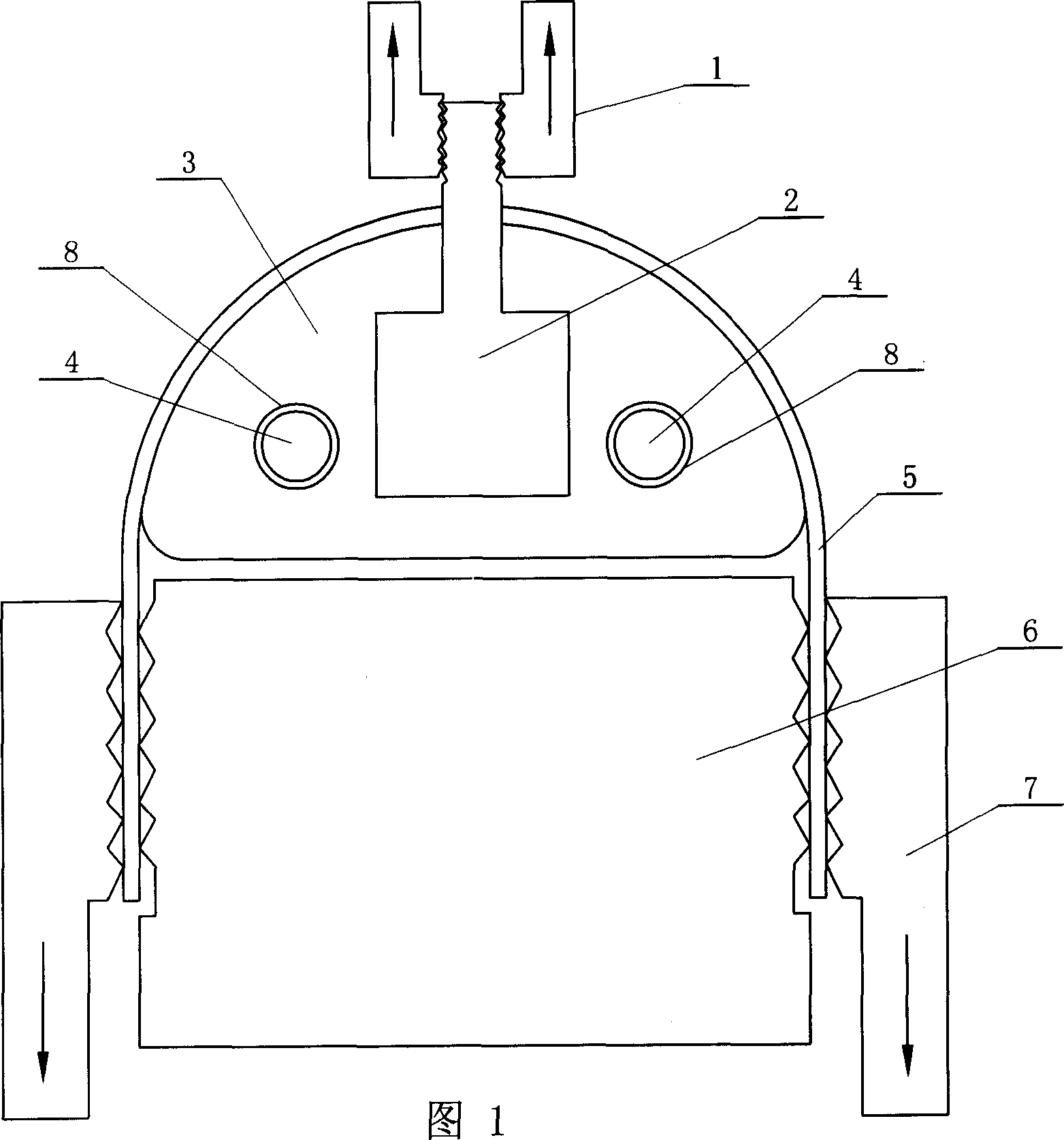
[0005] Specific embodiment one: (referring to Fig. 1) the technical scheme of the present embodiment is realized according to the following steps: one, will have the side of pipe material 5 of certain length axially incise, each 1 / 4 circle of otch both sides The long pipe is flattened, and the remaining pipes are kept in an arc shape; 2. Pass the semicircular rod 3 with the same diameter as the pipe inner diameter through the inner wall of the pipe 5, and the two ends of the semicircular rod 3 pass through the connecting body 2. Connect with the upper fixture 1 of the material tensile testing machine; 3. Place the clamping mandrel 6 with a width equal to the inner diameter of the pipe 5 between the two ends of the flattened pipe 5, and use the lower clamp of the material tensile testing machine to The clamp 7 clamps the two ends of the flattened pipe 5 on the clamping mandrel 6; 4. Start the material tensile testing machine to pull the upper clamp 1 and the lower clamp 7, so th...

specific Embodiment approach 2

[0006] Specific embodiment two: (referring to Fig. 1) the difference between this embodiment and specific embodiment one is that a round hole 8 is provided in the rod body of the semicircular rod 3, and an electric heating rod 4 is provided in the round hole 8 for use. When heating the pipe material 5, the heating temperature of the pipe material 5 is 20-800°C. The hoop tensile properties of the pipe 5 at different temperatures can be measured by heating the pipe 5 to a certain temperature and then stretching. Other process conditions and process steps are the same as the specific embodiment one.

specific Embodiment approach 3

[0007] Embodiment 3: (see FIG. 1 ) The difference between this embodiment and Embodiment 1 is that the lubricant molybdenum disulfide is placed between the semicircular rod 3 and the pipe 5 . Good lubrication is maintained between the semicircular rod 3 and the pipe 5 to reduce the influence of friction on the deformation of the pipe, so that the deformation of the pipe is closer to the state of unidirectional tensile stress. Other process conditions and process steps are the same as the specific embodiment one.


PUM

PropertyMeasurementUnit
lengthaaaaaaaaaa

Abstract

The disclosed tube circumferential tension performance test method comprises: using a semi-circle bar with same radius to cross the tube, starting up the testing machine to drive the upper and lower clamp, deforming the tube, and obtaining the test data. Compared to prior art, the benefit of this invention include: 1. changing no tube performance; 2. obtaining better testing result.

Description

technical field [0001] The invention relates to a method for testing the hoop performance of pipe materials. Background technique [0002] In many industrial fields, pipes, especially circular cross-section pipes, are the most common and widely used materials. Pipes are sometimes used as load-bearing structural parts, such as common frames in the construction industry or pipelines in high-pressure systems; in some cases, secondary processing of pipes is required, such as bending, flaring, reducing diameter, bulging, etc. Different usage conditions have different performance requirements for pipes. For example, if the pipe is used to transport high-pressure liquid or gas, the pipe needs to have sufficient strength to withstand the internal high pressure; if the pipe needs to be processed twice, the pipe is required to have a certain plastic deformation capacity. The most commonly used method to evaluate the plastic deformation ability of materials is the uniaxial tensile te...

Claims


Application Information

Patent Timeline
Patent Type & Authority Applications(China)
IPC IPC(8): G01N3/08
Inventor 何祝斌苑世剑张吉
Owner HARBIN INST OF TECH
Why Eureka
Try Eureka