Industrial electromagnetic heating process, apparatus and use

A heating method and electromagnetic induction heating technology, which are applied in the application field of the aforementioned method and device, can solve the problems of strong coil magnetic field interference, low heating power density, and the inability to install and use circular electromagnetic induction heating coils, etc., and achieve wide application range, The effect of increasing the heating power density

Inactive Publication Date: 2006-11-22
黄克
View PDF1 Cites 14 Cited by
  • Summary
  • Abstract
  • Description
  • Claims
  • Application Information

AI Technical Summary

Problems solved by technology

[0004] 1. In practical applications, the installation distance between the two coils is required to be ≥50mm, otherwise strong magnetic field interference will be generated between the coils, which will affect the normal operation of the electromagnetic controller
[0005] 2. It is not suitable for heating equipment with a large diameter pipe, because under the premise of maintaining a suitable inductance, the number of coils wound with a large diameter must be reduced, and the thermal efficiency will be reduced.
[0006] 3. Some pipes are long, and some pipes have flanges or dies in the middle, and the circular electromagnetic induction heating ring cannot be installed and used.
[0008] 1. The inductance per unit area is low, which is only suitable for low-power heating equipment
[0009] 2. The distance between the coil and the heated metal equipment is required to be large, the thermal efficiency is low, and the energy saving effect is not very good
[0010] The disadvantage of the electromagnetic induction heating coils with the above two structures is that the heating power density per unit area is small, which is not suitable for equipment that requires high heating power density, which limits their wide application.

Method used


Image

  • Industrial electromagnetic heating process, apparatus and use
  • Industrial electromagnetic heating process, apparatus and use
  • Industrial electromagnetic heating process, apparatus and use

Examples


Embodiment 1

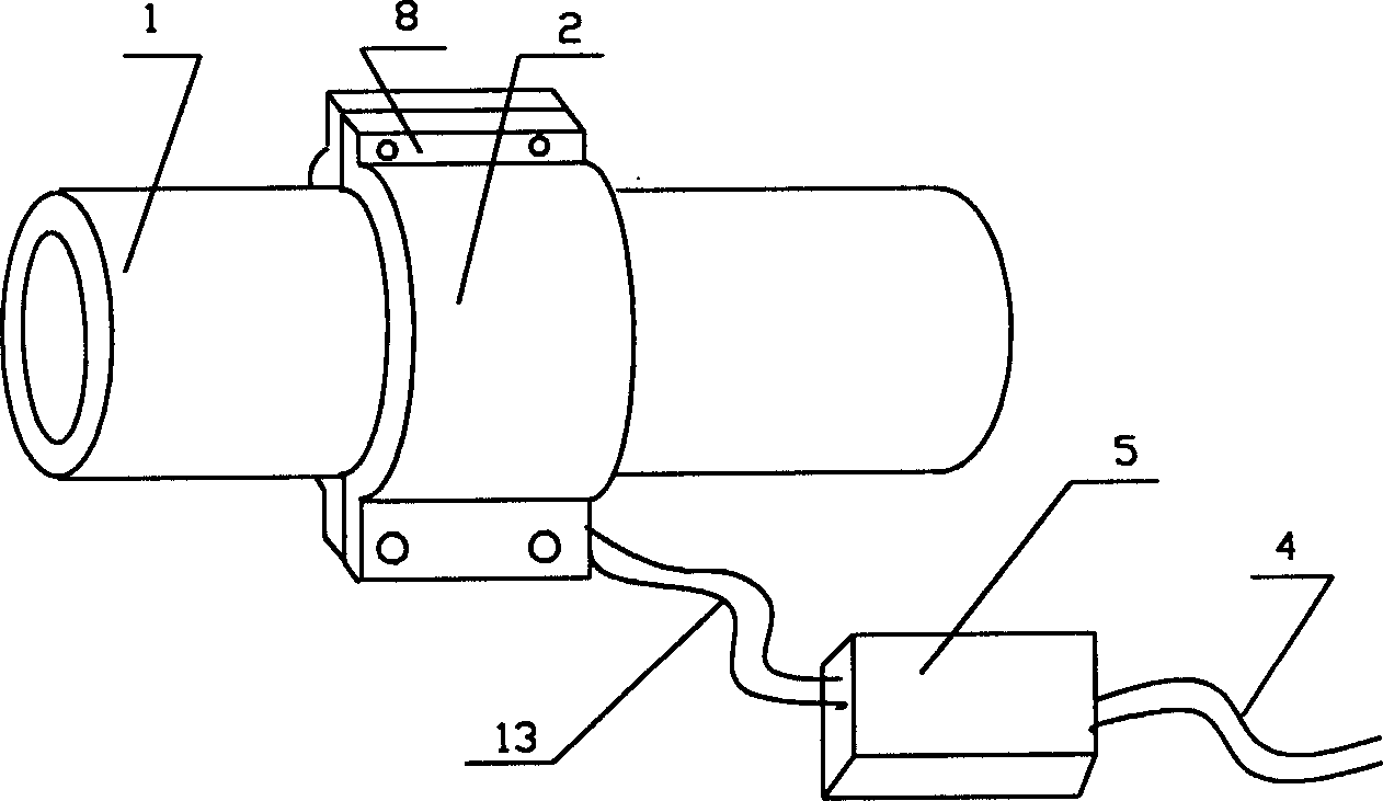
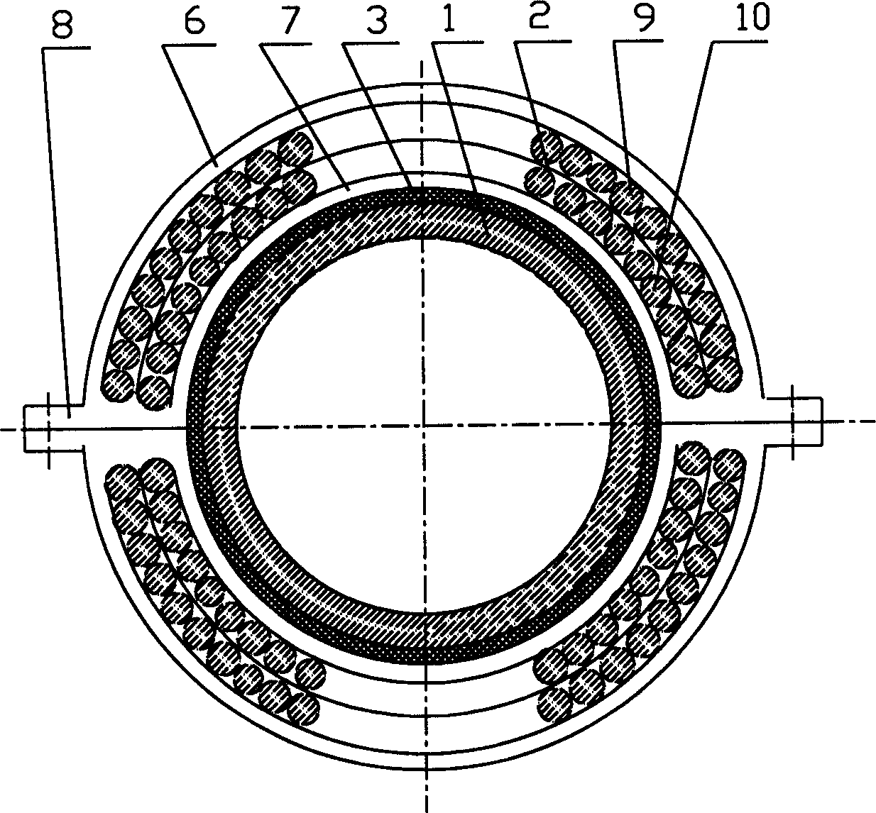
[0031] From attached figure 1 and figure 2 It can be seen that the present invention is a composite laminated electromagnetic induction heating coil, comprising a composite laminated electromagnetic induction heating coil 2, the composite laminated electromagnetic induction heating coil 2 is installed on the outside of the metal pipe 1 and communicated with the electromagnetic controller through a wire 13 5 phases, and the electromagnetic controller 5 is connected to the external power supply through the power line 4. The composite laminated electromagnetic induction heating coil 2 has no magnetic core, and a heat insulating material layer 3 is provided between its inner surface and the outer surface of the metal pipe 1. It is characterized in that: the composite laminated electromagnetic induction heating coil 2 is electrically The magnetic induction heating method is heated by double-layer stacked electromagnetic induction heating coils. A composite laminated electromagn...

Embodiment 2

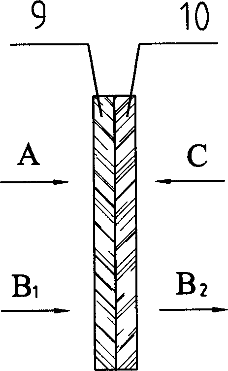
[0033] The principle of embodiment 2 is the same as that of embodiment 1. The laminated composite laminated electromagnetic induction heating coil is also a double-layer electromagnetic heating coil, but the shape of the composite laminated electromagnetic induction heating coil is made according to the shape of the applied pipeline. It has an arc-shaped structure and is composed of multiple arc-shaped composite laminated electromagnetic induction heating coils to form a complete circle. Each double-layer composite laminated electromagnetic induction heating coil is wrapped by an outer jacket and an inner jacket made of insulating materials, and A connector for connecting the composite laminated electromagnetic induction heating coils of each arc-shaped structure is provided at the junction of the outer jacket and the inner jacket of each section of the composite laminated electromagnetic induction heating coil, and the composite laminated electromagnetic induction heating coils...

Embodiment 3

[0035] Embodiment 3 is a planar composite laminated electromagnetic induction heating coil. The number of coils laminated by each composite laminated electromagnetic induction heating coil is four layers, and the coils of each layer are made of plane spiral winding and then laminated. Together, the coils are connected in series, and the wires of each adjacent coil are connected end to end; that is, the upper coil is spirally wound from the outside to the inside, the wire tail is located at the innermost coil, and the next coil The wire ends of the coil are spirally wound from the inside to the outside, so the wire ends of the next layer of coils just meet the wire ends of the upper layer of coils. And the four coils are made by winding a wire. The composite laminated electromagnetic induction heating coil is also wrapped by an insulating material, and a connector for fixing the composite laminated electromagnetic heating coil can be arranged outside the insulating material. T...


PUM


Abstract

The invention relates to an industrial electromagnetic heating method and relative device. Wherein, said method comprises: coating multilayer electromagnetic induction heating coil plane or arc on the frame of heated metal container or tube; or using electromagnetic induction to directly heat the metal container or tube; it mounts the multilayer electromagnetic induction heating coil formed by at least two layer of electromagnetic coils outside the heated metal container or tube; the magnetic lines of layered by electromagnetic heating coils functions the heated metal container or tube; the whole compound multilayer electromagnetic induction heating coil heating method comprises: the rectification circuit transforms the external alternative voltage into direct-current voltage, the control circuit transforms the direct-current voltage into high-frequency voltage, then functions the high-frequency voltage on the compound multilayer electromagnetic induction heating coil, to use electromagnetic induction to heat the material inside the metal container or tube.

Description

technical field [0001] The invention belongs to an electromagnetic heating method and device, in particular to an electromagnetic heating method and device applied in industry. The present invention also relates to the application of the aforementioned method and device, which are mainly used in plastic (rubber) molding machinery, pipelines for transporting crude oil and heavy oil, and other industrial heating places. Background technique [0002] In industrial production, it is often necessary to heat materials. Now there are two general industrial heating methods, one is to use fuel for heating, and the other is to use electric energy for heating. With the development and progress of industry, more and more industrial and mining sites use electric energy to heat, but now most of the electric heating is still directly heated by electric heating devices, and then heated by heat conduction. For example, the heating method of plastic processing machinery is to use the electr...

Claims


Application Information

Patent Timeline
Patent Type & Authority Applications(China)
IPC IPC(8): H05B6/02H05B6/40H05B6/44
Inventor 黄克
Owner 黄克
Why Eureka
Try Eureka