Discharge lamp lighting circuit

A technology for discharge lamps and circuits, which is applied in the direction of discharge lamps, circuits, electric light sources, etc., can solve the problems of different settings and unrealistic methods of setting the lighting frequency, and achieve the effect of ensuring stability

Inactive Publication Date: 2006-11-22
KOITO MFG CO LTD
View PDF1 Cites 8 Cited by
  • Summary
  • Abstract
  • Description
  • Claims
  • Application Information

AI Technical Summary

Problems solved by technology

[0010] At a lighting frequency above 1MHz, the frequency at which acoustic resonance occurs is discontinuous and becomes a discrete value. Therefore, a stable arc can be obtained by selecting a frequency that does not produce acoustic resonance a

Method used


Image

  • Discharge lamp lighting circuit
  • Discharge lamp lighting circuit
  • Discharge lamp lighting circuit

Examples


Embodiment Construction

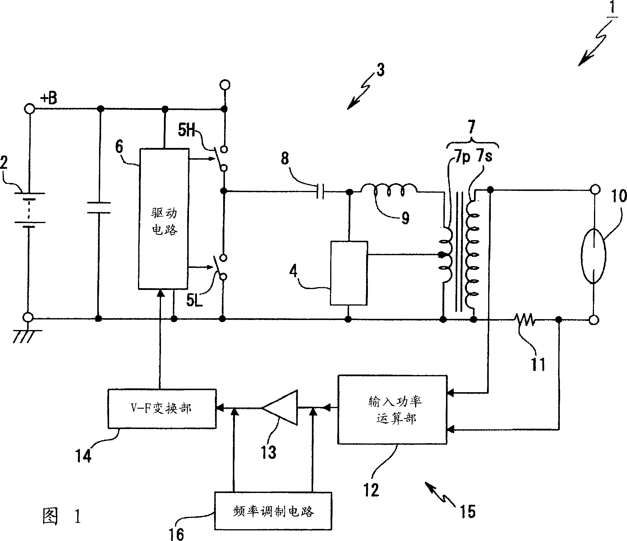
[0033] 1 is a diagram showing an example of a basic configuration of the present invention. A discharge lamp lighting circuit 1 includes a DC-AC conversion circuit 3 and a starting circuit 4 for receiving power from a DC power supply 2 .

[0034] The DC-AC conversion circuit 3 is configured to receive a DC input voltage (refer to "+B" in the figure) from the DC power supply 2 to perform AC conversion and voltage boosting. In this example, there are two switching elements 5H, 5L, and a drive circuit 6 for driving them. That is, one end of the switching element 5H on the high potential side is connected to the power supply terminal, the other end of the switching element is grounded via the switching element 5L on the low potential side, and the respective elements 5H, 5L are alternately turned on by a signal from the drive circuit 6 . Pass / Closed. In addition, in the drawing, the elements 5H and 5L are represented by symbols of switches for simplification, but semiconductor sw...


PUM


Abstract

A discharge lamp lighting circuit 1 includes a direct current-alternating current converting circuit 3 , a starting circuit 4 , controlling means 15 for controlling power, switching elements 5 H, 5 L driven by the controlling means 15 and a series LC resonance circuit ( 7 p , 8, 9 ). A frequency modulating circuit is provided for restraining acoustic resonance by modulating a frequency of driving the switching element. When a basic frequency related to the drive frequency is equal to or higher than 1 MHz, a modulation width is set to be equal to or higher than 20 kHz.

Description

technical field [0001] The present invention relates to a technology for countermeasures against acoustic resonance in a high-frequency lighting circuit of a discharge lamp. Background technique [0002] A lighting circuit for a discharge lamp such as a metal halide lamp used as a light source for automobile lighting is known to include a DC power supply circuit having a DC-DC converter structure, a DC-AC conversion circuit, and a starting circuit. For example, after the DC input voltage from the battery is converted into a desired voltage in the DC power supply circuit, it is converted into an AC output by the DC-AC conversion circuit of the subsequent stage, and the starting signal is superimposed on it to provide the discharge lamp (such as , refer to Patent Document 1). [0003] In the lighting control of the discharge lamp, the no-load output voltage (hereinafter referred to as "OCV") before the discharge lamp is lit (when it is extinguished) is controlled, and after t...

Claims


Application Information

Patent Timeline
IPC IPC(8): H05B41/288
CPCH05B41/2887Y02B20/00Y10S315/05Y10S315/07
Inventor 松井浩太郎市川知幸八木操一
Owner KOITO MFG CO LTD
Why Eureka
Try Eureka