Thread fixing structure of thermal-state magnesium alloy component

A fixed structure, magnesium alloy technology, applied in the direction of threaded fasteners, nuts, connecting components, etc., can solve the problems of thread wear, bolt looseness, breakage, etc., to achieve the effect of ensuring firm connection, avoiding loose connection, and simple structure

Inactive Publication Date: 2006-11-29
LONCIN MOTOR
View PDF0 Cites 6 Cited by
  • Summary
  • Abstract
  • Description
  • Claims
  • Application Information

AI Technical Summary

Problems solved by technology

[0005] The purpose of the present invention is to provide a thread fixing structure for hot magnesium alloy parts, which can solve the problem that the threads in the screw holes of the magnesium alloy parts are prone to severe wear or fracture when the magnesium alloy parts are in a hot working state with a high temperature for a long time Phenomenon, the bolts fixed in the screw holes will loosen or even fall off.

Method used


Image

  • Thread fixing structure of thermal-state magnesium alloy component
  • Thread fixing structure of thermal-state magnesium alloy component
  • Thread fixing structure of thermal-state magnesium alloy component

Examples


Embodiment 1

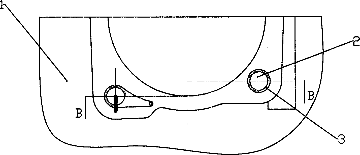
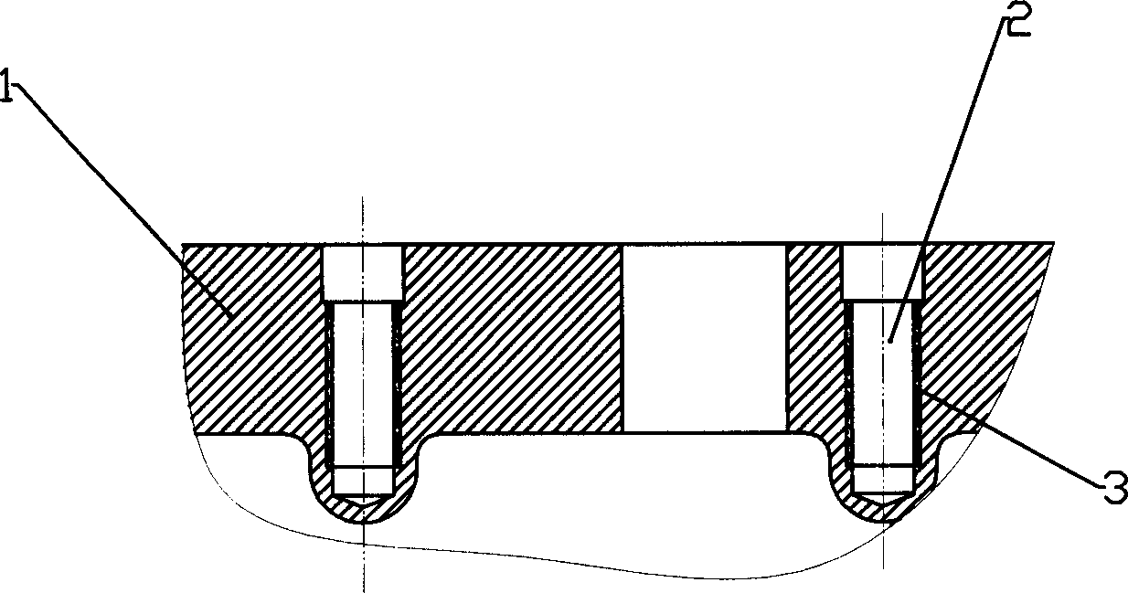
[0021] like figure 1 and figure 2 Shown is a right crankcase body 1, which is formed by die-casting of magnesium alloy material. At the joint surface of the cylinder mouth of the crankcase body, the parts for setting screw holes are respectively embedded with the joint surface perpendicular to the joint surface and facing into the box body. The extended hard insert 3 is machined into the hard insert 3 with a screw hole 2 perpendicular to the joint surface. The hard insert 3 is a steel sleeve, the outer wall of which is processed with external threads, and is embedded in the magnesium alloy right crankcase 1 through the external threads. This structure allows the insert 3 to be inserted into the magnesium alloy right crankcase 1 Loaded after the die-casting process is completed. More ideally, the thread of the external thread of the hard insert 3 is thicker than the thread of the internal thread of the screw hole 2, so as to enhance the strength of the thread on the magnesiu...

Embodiment 2

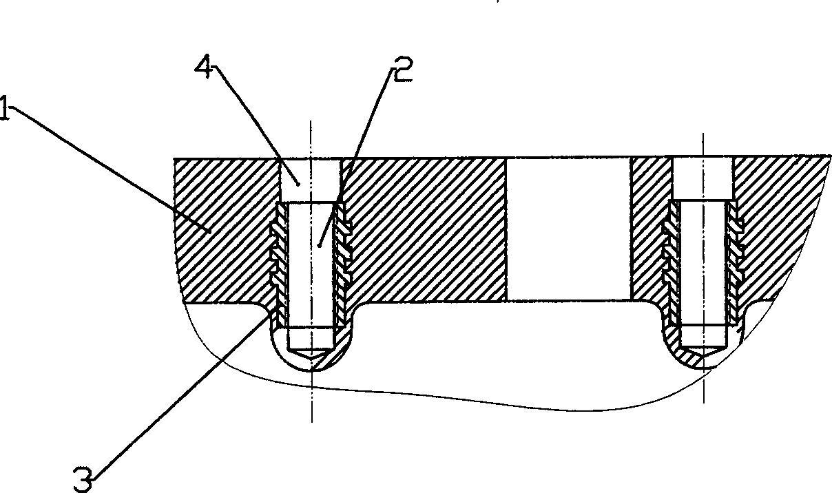
[0023] image 3 It is another embodiment of the screw fixing structure of the hot magnesium alloy parts of the present invention. The hard insert 3 made of hard materials such as cast iron or aluminum alloy, which is processed with internal threads, is die-cast on the magnesium alloy crankcase body 1. When forming, it is pre-embedded in the box body and molded integrally with the box body 1, so that the firmness of the combination of the hard insert 3 and the magnesium alloy crankcase body 1 is guaranteed.

[0024] In order to improve the solidity of the combination of the hard insert 3 and the hot magnesium alloy crankcase 1, the combination Figure 4 and Figure 5 As shown, a groove or a protrusion 31 structure can be set on the outer surface of the hard insert 3, and the groove or protrusion structure can be continuous in the circumferential direction of the hard insert 3, or can be as Figure 5 Interrupted grooves or protrusions 31, shown here, also prevent rotation of t...

Embodiment 3

[0027] The hard insert 3 is directly assembled with the magnesium alloy crankcase 1 through interference fit, and the hard insert 3 and the magnesium alloy parts are combined more firmly due to thermal expansion under hot working conditions.

[0028] Although the examples in this embodiment all take the crankcase of a motorcycle engine as an example, those skilled in the art can understand that the present invention is applicable to the screw fixing structure of magnesium alloy parts in various hot working states.


PUM

PropertyMeasurementUnit
yield strengthaaaaaaaaaa

Abstract

The invention discloses a screw fixation structure of liquid magnesium alloy that includes magnesium alloy section and hardness embedded component. The hardness embedded component is fixed in the magnesium alloy section and has screw. The structure could avoid loosing phenomena, and has simple structure.

Description

technical field [0001] The invention relates to a thread fixing structure of a magnesium alloy part, in particular to a thread fixing structure of a magnesium alloy part in a hot working state. Background technique [0002] Magnesium alloy has good thermal conductivity, non-toxic, non-magnetic. The parts made of magnesium alloy are light in weight, about 2 / 3 of that of aluminum alloy die-casting parts, and have good processing performance, can absorb vibration, have good damping performance, and have good impact strength and compression strength. However, the high temperature creep resistance of magnesium alloy is poor. At room temperature, the yield strength of magnesium alloy is 160MPa, which is almost the same as that of aluminum alloy at 165MPa; at a temperature of 90°C, the creep strength drops to 90MPa after 100 hours, which is only about 56% of the strength at room temperature; At 120°C, the creep strength after 100 hours is only 48MPa, which is only about 30% of th...

Claims


Application Information

Patent Timeline
Patent Type & Authority Applications(China)
IPC IPC(8): F16B37/00
Inventor 李必胜罗章瑜付无尚
Owner LONCIN MOTOR
Why Eureka
Try Eureka