Manufacturing method of inducer

A manufacturing method, inductor technology, applied in the direction of inductors, inductors/transformers/magnets manufacturing, fixed inductors, etc., can solve problems such as high difficulty in coplanarity, abnormal operation of inductors, and damage to insulation, etc., to achieve speed-up and efficiency effect

Inactive Publication Date: 2006-11-29
LINKCOM MFG
View PDF0 Cites 6 Cited by
  • Summary
  • Abstract
  • Description
  • Claims
  • Application Information

AI Technical Summary

Problems solved by technology

[0005] (1) As far as the material is concerned, the traditional coil part 10 is made of "enameled wire", and the "varnish" on the outer layer of the wire is mainly used for insulation, avoiding the conductive bare wire and the magnetic base 12 made of iron powder die-casting Form a short circuit; the problem is that in the process of the "enameled wire" passing through the relevant tools, it is easy to cause "cracks" on the surface of the "varnish" due to the increase of external tension, which destroys the insulation, and it is easy to make the conductive bare wire A short circuit with the magnetic base 12 will not only make the inductor unable to operate normally, but may also impact the connected system or equipment end and cause damage
[0006] (2) The structure of the magnetic base 12 and the cover 13 made of iron powder die-casting is very fragile, and often breaks when the coil is produced or assembled, making the quality of the product unstable; especially when the coil is assembled with the above-mentioned prior art, Because will bend pin portion 11,11a and cover body 13 joints (as figure 2 As shown), considerable force must be applied to complete this process, so that the magnetic seat shaft 122 and cover 13 that are interfered by the force will be affected and more easily damaged
[0007] (3) Because the pins 11 and 11a of the coil are the extensions of the two ends of the coiled coil part 10, the relative positions of the two pins 11 and 11a are one high and one low. When the coil part 10 is placed on the magnetic base After the shaft part 122, it is very difficult to bend the two leg parts 11, 11a to the bearing plate 131 of the cover body 13 in a very precise manner, and keep them coplanar, which is often limited by the coil part 10 during the coiling process. Dimensional errors are generated, which directly affect the reserved length of the pins 11, 11a, resulting in the joint surfaces 111, 111a of the two pins 11, 11a being unable to be flush, resulting in a problem when connecting to an external circuit. troubled

Method used


Image

  • Manufacturing method of inducer
  • Manufacturing method of inducer
  • Manufacturing method of inducer

Examples


Embodiment Construction

[0023] In conjunction with the accompanying drawings, the implementation process of the present invention is described in detail with preferred embodiments:

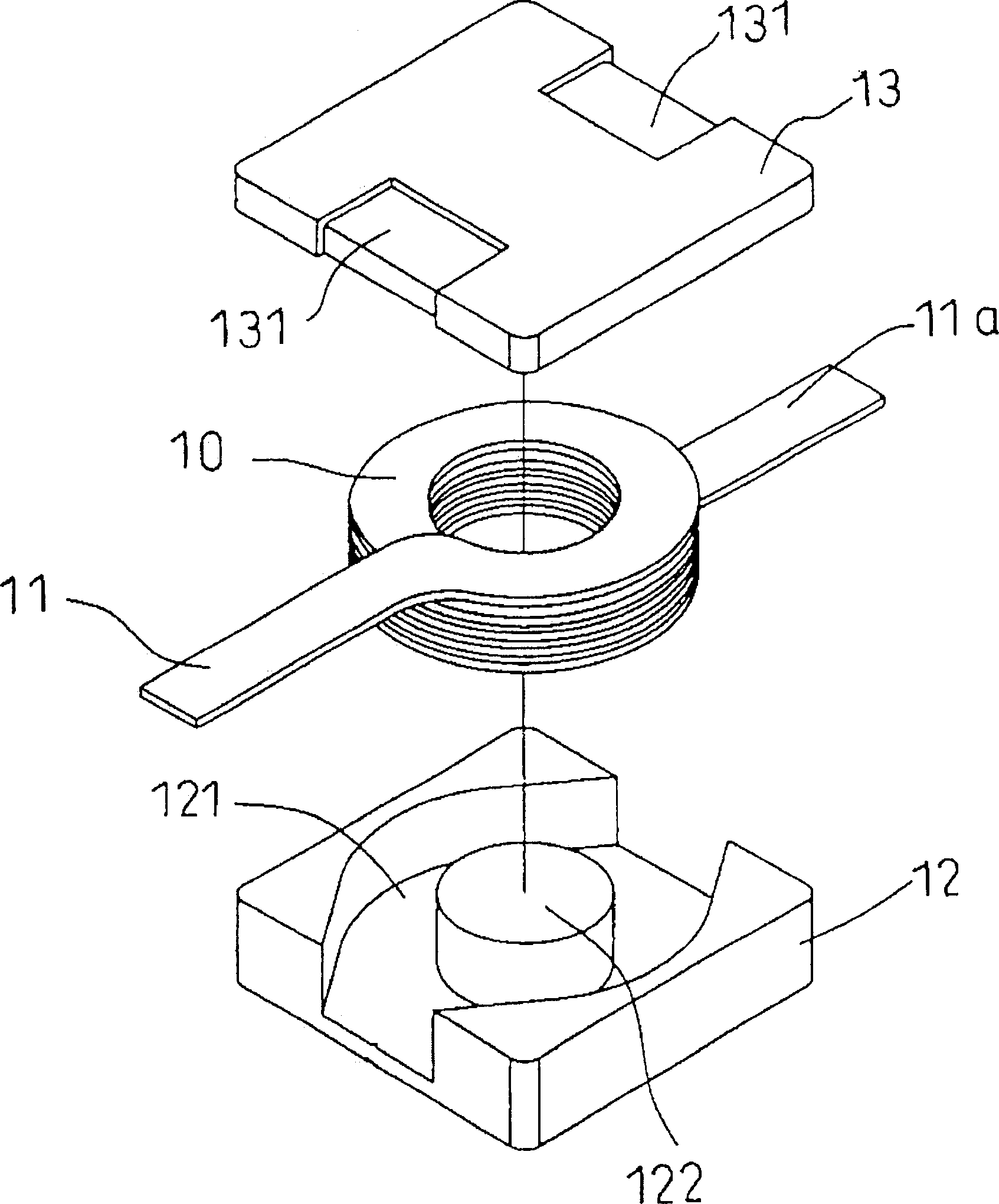
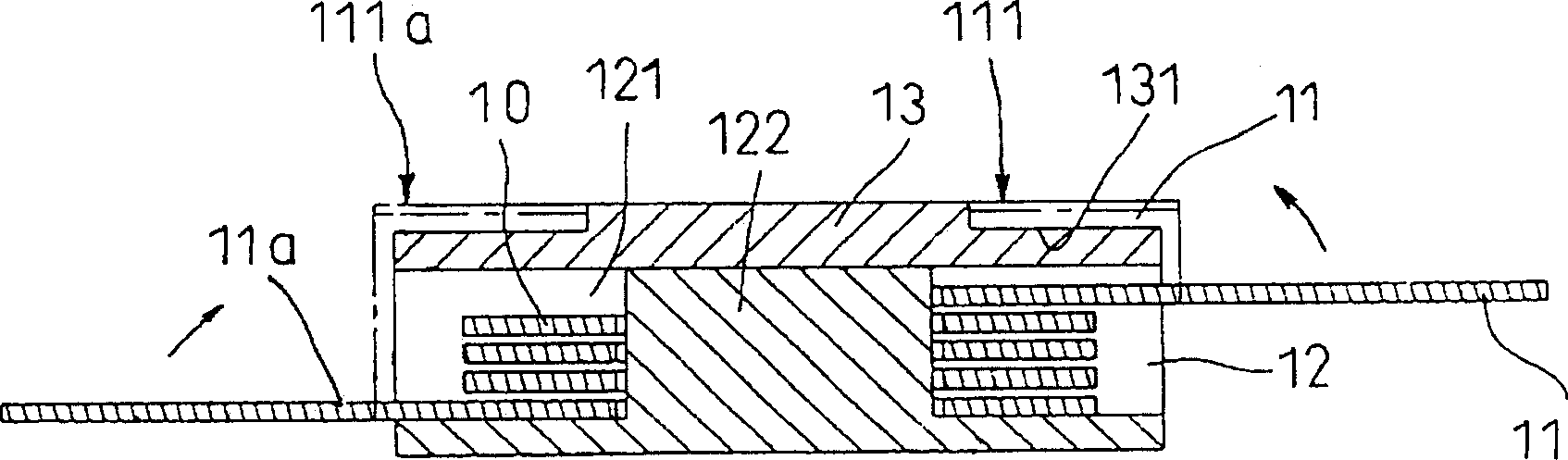
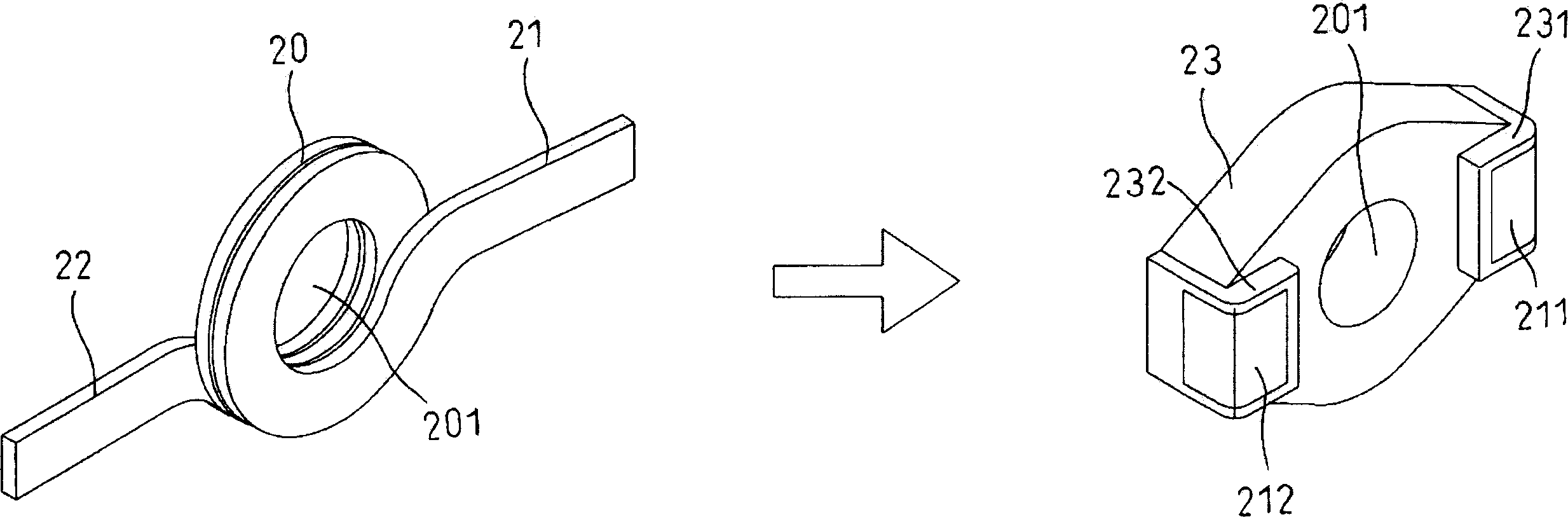
[0024] image 3 , Fig. 4, Fig. 5 are the main structural diagrams of the inductor of the present invention, as shown in the figure, the inductor mainly consists of a coil part 20, the pin parts 21, 22 extending at the two ends of the coil part 20, and one by iron powder die-casting The formed magnetic permeable base 30 and cover 40 are formed.

[0025] The manufacturing flow of inductor of the present invention comprises:

[0026] Step 1, take a flat bare wire and wind it into a coil part 20, and reserve a pin part 21, 22 at both ends of the coil part 20;

[0027] Step 2, bending the two pin portions 21 and 22 in the same direction to the same height;

[0028] Step 3, spray an insulating layer on the surface of the coil part 20 and the two pin parts 21, 22, such as insulating varnish;

[0029] Step 4: inject an insul...


PUM


Abstract

A method for preparing inductor includes winding a flat bare wire to be a coil and holding connection pin at two ends of coil, folding two connection pins towards the same direction at the same height, spraying an insulation layer on surface of two connection pins and coil, injecting a covering body in range of coil and two connection pins for positioning them, using a partial connection pin being exposed externally as connecting face to be connected with external circuit and setting said covering body in magnetic conduction base made by iron powder and in cover.

Description

technical field [0001] The invention relates to a manufacturing method of a flat coil inductor. The volume of the inductor is light, thin and small, and it usually has a current limiting function for electronic circuits. Background technique [0002] Inductors with flat coils have a thinner volume, larger conduction area, can withstand large currents and are easy to assemble, and are widely used in consumer electronics products. Usually, the inductor is connected to the electronic circuit on the product or system side, and the circuit has a contribution such as current limiting. [0003] Such as figure 1 , figure 2 In the prior art shown, the inductor of the flat coil usually consists of: a flat coiled coil part 10, pin parts 11, 11a extending from both ends of the coil part 10, and an iron powder die-cast The magnetic permeable base 12 and the cover body 13 are composed; wherein, the magnetic permeable base 12 has an open chamber 121, and a shaft portion 122 is arranged...

Claims


Application Information

Patent Timeline
Patent Type & Authority Applications(China)
IPC IPC(8): H01F41/00H01F17/04H01F37/00
Inventor 林志鸿
Owner LINKCOM MFG
Why Eureka
Try Eureka