Method for treating ammonia nitrogen in charking deposed ammonia

A technology of ammonia water and ammonia nitrogen, which is applied in the direction of chemical instruments and methods, separation methods, water/sewage treatment, etc., can solve the problem that wastewater is difficult to meet the national water quality discharge standards, the load of activated sludge biochemical treatment is large, and the removal rate of total ammonia nitrogen is low, etc. problems, to achieve significant energy-saving effects, reduce energy consumption, and reduce the ammonia nitrogen load

Inactive Publication Date: 2006-12-06
WUHAN UNIV OF SCI & TECH
View PDF4 Cites 9 Cited by
  • Summary
  • Abstract
  • Description
  • Claims
  • Application Information

AI Technical Summary

Problems solved by technology

[0005] In the above-mentioned technologies, the former adopts large ammonia distillation tower equipment, high operating temperature of water vapor desorption, high energy consumption, high cost, and low removal rate of total ammonia nitrogen, so that the ammonia nitrogen load of activated sludge biochemical treatment is relatively large
Therefore, the treatment of coking plant wastewater has been difficult to meet the national water quality discharge standards for a long time
The latter uses a through-flow sieve plate tower with large equipment and high operating temperature. In order to maintain the residual ammonia water in the through-flow sieve plate desorption tower at 85-90°C, multiple steam heaters are used to heat it, which consumes a lot of energy. , high cost and low removal rate of total ammonia nitrogen, so that the load of activated sludge biochemical treatment is relatively large
Therefore, the treatment of coking plant wastewater has been difficult to meet the national water quality discharge standards for a long time

Method used


Image

  • Method for treating ammonia nitrogen in charking deposed ammonia
  • Method for treating ammonia nitrogen in charking deposed ammonia
  • Method for treating ammonia nitrogen in charking deposed ammonia

Examples


Embodiment Construction

[0022] The technology of the present invention will be further described below in conjunction with the accompanying drawings.

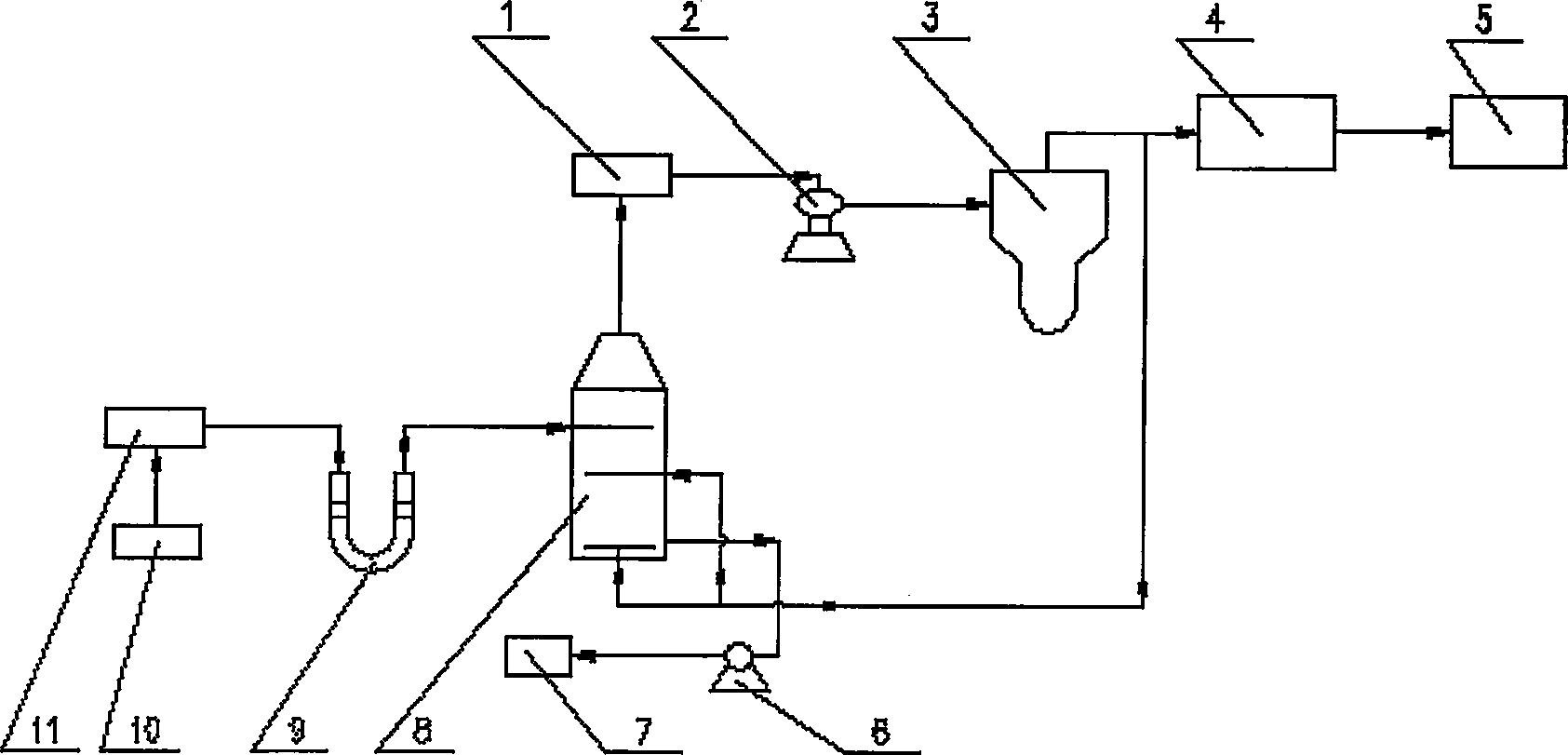
[0023] The chemical composition of a coking waste ammonia water [11] is: total ammonia 2-5g / L, volatile ammonia 1-2g / L, CO 2 1~2g / L, sulfide 0.2~2g / L, cyanide 0.04~0.14g / L, volatile phenol 1.3~2.5g / L, temperature 70~80℃. The technological process for treating ammonia nitrogen in the waste ammonia is as follows: figure 1 Shown:

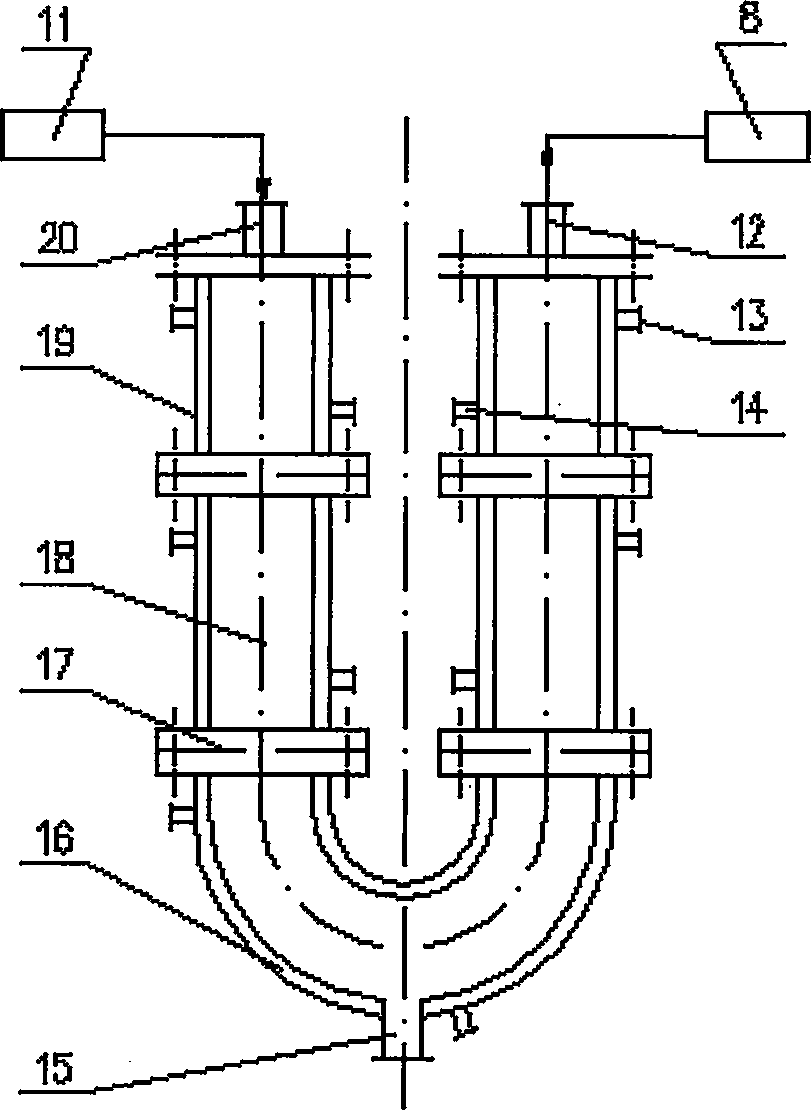
[0024] First add 15-35g / L Na in the above coking waste ammonia water [11] 2 CO 3 As a removal agent [10], adjust the pH value to 10-12, and then add Na 2 CO 3 The waste ammonia water [11] of removal agent [10] is sent into such as by pipeline figure 2 As shown, or adopt "a kind of fixed ammonium salt reactor" (CN200610019288.2), or adopt "a kind of cyclone reactor" (CN200620097103.5). The waste ammonia water [11] passes through the swirl plate [17] installed between each heat carrier jacket [19] from the liquid inlet [...


PUM


Abstract

This invention relates to a method for treating ammonia-nitrogen in waste coking ammonia solution. The method comprises: (1) adding desulfurizing agent 15-35 g/L to waste coking ammonia solution, and adjusting the pH value to 10-14; (2) introducing into a reactor for reaction; (3) introducing waste ammonium solution into an immersing-type blowing desorption unit, and introducing coke oven coal gas into the first and the second gas distributors below the liquid level of the desorption unit; (4) introducing desorbed waste ammonia into an active sludge treatment unit with a pump; (5) cooling the desorbed ammonia-containing coal gas, and introducing into a coke oven coal gas main pipe; (6) introducing mixed coal gas with a blower into an ammonium sulfate saturating unit, and reacting with sulfuric acid to obtain ammonium sulfate; (7) introducing most coal gas into a coarse benzene recovering unit, and sending to fuel gas plants or coke ovens; (8) introducing other coal gases into the immersing-type blowing desorption unit for recycling. This invention has such advantages as improved ammonia-nitrogen removal efficiency, saved energy, reduced cost, and lowered ammonia-nitrogen loading for biotreatment, and is environmentally friendly.

Description

technical field [0001] The invention belongs to the technical field of coking waste ammonia water treatment. In particular, it relates to a treatment method directly applied to ammonia nitrogen in residual ammonia water or waste ammonia water of a coking plant. Background technique [0002] In the remaining ammonia water produced during the production process of the coking plant, the ammonia nitrogen is composed of volatile ammonium salt and fixed ammonium salt, and the volatile ammonium salt has NH 4 OH, (NH 4 ) 2 S, NH 4 CN and (NH 4 ) 2 CO 3 , the fixed ammonium salt has NH 4 Cl and (NH 4 ) 2 SO 4 Wait. [0003] At present, coking plants at home and abroad generally use the steam method to remove ammonia nitrogen in the remaining ammonia water, that is, the remaining ammonia water after oil removal is heated to 90°C by the ammonia water heat exchanger, and then enters the upper part of the ammonia water distillation tower, and steam is passed into the bottom of...

Claims


Application Information

Patent Timeline
Patent Type & Authority Applications(China)
IPC IPC(8): C02F1/58C02F9/14C02F1/20C02F3/12B01D53/38
CPCY02A50/20Y02W10/10
Inventor 王光华文艳梁玉河魏松波左建平
Owner WUHAN UNIV OF SCI & TECH
Why Eureka
Try Eureka