Valve for switching double gas supplies in use for fuel gas heating apparatus

A technology of dual gas sources and switching valves, which is applied in the direction of multi-way valves, valve devices, engine components, etc., can solve the problems of dual gas source gas heaters without suitable gas source switching valves, etc., so as to facilitate the organization of production and sales, and facilitate Distributors and manufacturers, the effect of compact structure

Inactive Publication Date: 2006-12-06
PROCOM ELECTRIC APPLIANCES SHANGHAI
View PDF0 Cites 50 Cited by
  • Summary
  • Abstract
  • Description
  • Claims
  • Application Information

AI Technical Summary

Problems solved by technology

[0003] The purpose of this invention is to design a gas source switching valve that can be used for switching between two types of gas, and can be used with different gas sources to solve the problem that the current dual gas source gas heater is difficult to realize without a suitable gas source switching valve. And the dual gas source conversion valve for the gas heater that properly adjusts the air intake of the primary air inlet

Method used


Image

  • Valve for switching double gas supplies in use for fuel gas heating apparatus
  • Valve for switching double gas supplies in use for fuel gas heating apparatus

Examples


Embodiment 1

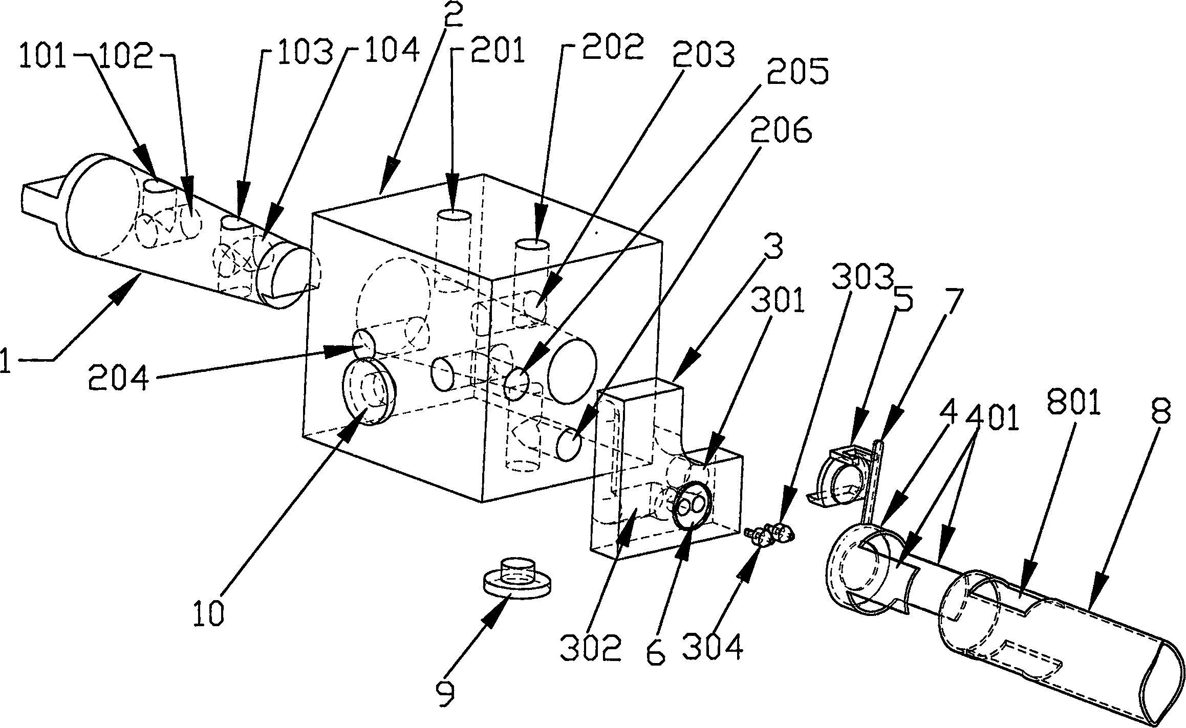
[0018] Such as figure 1 shown.

[0019] A dual gas source conversion valve for a gas heater, which includes a valve core 1 with a knob, a main valve body 2, a nozzle assembly 3 and a primary air inlet adjustment sleeve 4, wherein the nozzle assembly 3 and the main valve body 2 can be It is an integral structure, and it can also be a split structure as shown in the figure. The main valve body 2 is provided with an ODS inlet channel 201, a gas inlet channel 202, a high calorific value gas ODS outlet channel 203, and a low calorific value gas ODS outlet channel. 204, high calorific value gas outlet channel 205, low calorific value gas outlet channel 206, the nozzle assembly 3 is provided with an air channel 301 connecting the high calorific value gas outlet channel 205 and the high calorific value gas nozzle 303 and connecting the low calorific value gas outlet channel 206 and The air channel 302 of the low calorific value gas nozzle 304, the valve core 1 is provided with a chan...

Embodiment 2

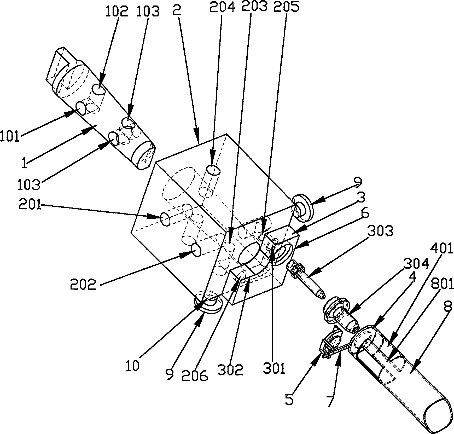
[0021] Such as figure 2 shown.

[0022] A dual gas source conversion valve for a gas heater, which includes a valve core 1 with a knob, a main valve body 2, a nozzle assembly 3 and a primary air inlet adjustment sleeve 4, wherein the nozzle assembly 3 and the main valve body 2 can be It is an integral structure, and it can also be a split structure as shown in the figure. The main valve body 2 is provided with an ODS inlet channel 201, a gas inlet channel 202, a high calorific value gas ODS outlet channel 203, and a low calorific value gas ODS outlet channel. 204, high calorific value gas outlet channel 205, low calorific value gas outlet channel 206, the nozzle assembly 3 is provided with an air channel 301 connecting the high calorific value gas outlet channel 205 and the high calorific value gas nozzle 303 and connecting the low calorific value gas outlet channel 206 and The air channel 302 of the low calorific value gas nozzle 304, the valve core 1 is provided with a cha...


PUM


Abstract

The present invention relates to a double gas source conversion valve for gas warmer. It includes the following several portions: valve core with knob, main valve body, nozzle assemblage and once gas inlet regulation cover. The main body of valve core can be turnably insert-mounted in the main valve body, its one end is passed through said main valve body and is equipped with a shifting fork, the nozzle assemblage is mounted on side surface of said main valve body, the high combustion valve gas nozzle and low combustion value gas nozzle are mounted in the gas outlet on the nozzle assemblage, the gas feeding end of said once gas inlet regulation cover is cover-mounted on the gas outlet, its another end is inserted into main combustor, on the described once gas inlet regulation cover a shifting bar is fixedly mounted, one end of said shifting bar is inserted into the shifting fork. Said invention can convertibly use two kinds of gas.

Description

technical field [0001] The invention relates to a gas heater component, in particular to a dual gas source gas heating component, in particular to a dual gas source switching valve for a gas heater. Background technique [0002] At present, with the continuous improvement of transportation technology and the increasing shortage of oil resources, natural gas, biogas and other low calorific value gases have gradually entered people's daily life, and the single energy source in cities is being gradually broken by the multi-energy supply system. At the same time, it has become possible to connect the gas supply pipelines of coal gas, natural gas, liquefied petroleum gas, biogas and other energy sources. People can choose the appropriate gas to use according to market price changes and gas supply conditions. Taking the gas heater as an example, in the past, it was a single structure dedicated to liquefied petroleum gas or natural gas. Due to the different calorific values ​​of va...

Claims


Application Information

Patent Timeline
Patent Type & Authority Applications(China)
IPC IPC(8): F16K11/08F16K11/083
Inventor 戴长林
Owner PROCOM ELECTRIC APPLIANCES SHANGHAI
Why Eureka
Try Eureka