Plate heat exchanger with no deposited scale, and heat exchange mode

A plate heat exchanger, scale deposition technology, applied in the direction of heat exchanger types, indirect heat exchangers, heat exchange equipment, etc., can solve the problem of not correctly reflecting the physical process of heat transfer along the flow of plate heat exchangers, to achieve Save fuel and power resources, improve heat exchange efficiency, and improve the effect of ecological environment

Inactive Publication Date: 2006-12-06
王正方 +1
View PDF1 Cites 4 Cited by
  • Summary
  • Abstract
  • Description
  • Claims
  • Application Information

AI Technical Summary

Problems solved by technology

when Δt min = t h2 -t c2 → When 0 (this is the actual situation of the plate heat exchanger), the function Δt mp There is a singularity, which cannot correctly reflect the real physical process of the plate heat exchanger's downstream heat transfer

Method used


Image

  • Plate heat exchanger with no deposited scale, and heat exchange mode
  • Plate heat exchanger with no deposited scale, and heat exchange mode
  • Plate heat exchanger with no deposited scale, and heat exchange mode

Examples


Embodiment 1

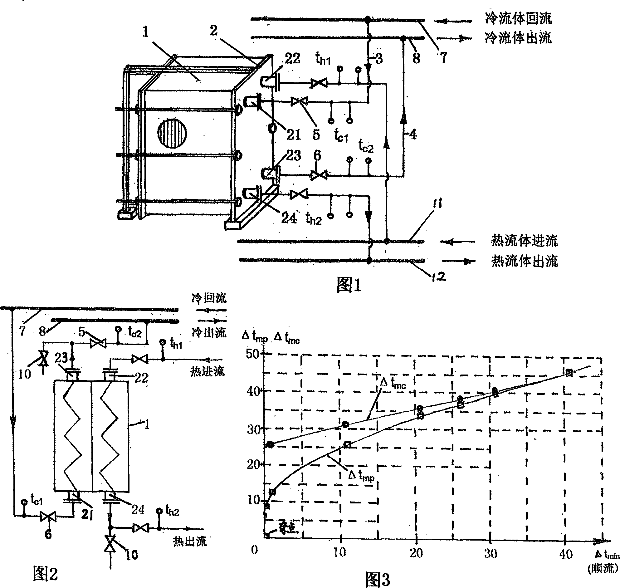
[0053] As shown in Figure 1, on the side of the fixed compression plate 2 of the ordinary plate heat exchanger 1, the cold fluid inlet 21 on the upper part of the fixed compression plate 2 is connected to the cold fluid return main pipeline 7 with the pipeline 3 equipped with the valve 5 With the pipeline 4 that valve 6 is installed, the cold fluid outlet 23 on the bottom of the fixed compression plate 2 is connected with the cold fluid outflow main pipeline 8, the hot fluid inlet 22 communicates with the hot fluid inlet main pipeline 11, and the hot fluid outlet 24 It communicates with the thermal fluid outflow main pipeline 12. The feature of this pipeline connection is that when the valve 5 and the valve 6 are in an open state, the cold fluid in the return main pipeline 7 can flow into the plate heat exchanger 1 from the cold fluid inlet 21 on the upper part of the fixed pressing plate 2, and the cold fluid can flow into the plate heat exchanger 1. The fluid flows from top ...

Embodiment 2

[0055] Such as Figure 9 As shown, on the basis of the heat exchange between the cold and hot fluids described in Embodiment 1, a high-frequency anti-scaling and descaling system such as that provided by the utility model patent ZL96 2 38603.0 is installed on the cold fluid return main pipeline 7 The water treatment device 9, even if the cold fluid is ground water with relatively high hardness, the heat exchange plate will not be hard scaled, and the purpose of neither depositing scale nor hard scale can be achieved. Figure 9 It is a parallel structure of multiple plate heat exchangers. The cold fluid inlets 21 communicate with the cold fluid return main pipeline 7 respectively, the hot fluid inlets 22 communicate with the hot fluid inlet main pipeline 11 respectively, and the cold fluid outlets 23 communicate with the cold fluid outlet respectively. The main pipeline 8 communicates, and the thermal fluid outlets 24 communicate with the thermal fluid outflow main pipeline 12 re...

Embodiment 3

[0057] On the basis of installing a high-frequency anti-scaling and descaling water treatment device on the cold fluid return main pipeline 7 described in Example 2, and then install a water treatment device on the hot fluid inflow main pipeline 11 as provided by the utility model patent ZL96 2 38603.0 High-frequency anti-scaling and descaling water treatment device, so that both cold and hot fluids can use non-demineralized water, and it can realize that there is no deposited scale and mud in the plate heat exchanger, and no hard scale chemically adsorbed.

[0058] The present invention proposes a method for forming a plate heat exchanger without scale deposits, by changing the conventional connection mode of the cold fluid inlet and outlet pipes of the common plate heat exchanger, that is, by exchanging the positions of the conventionally connected inlet and outlet pipes , change the normal flow direction of the cold fluid in the heat exchanger, so that the original cold and ...


PUM


Abstract

The present invention relates to an improvement technique of heat exchanger, in the concrete, it is a plate type heat exchanger which does not produce water scale deposit and its water exchange mode. It is characterized by that in fixed tight-pressing plate side of general plate-type heat exchanger, the cold fluid inlet of upper portion of said fixed tight-pressing plate is connected with cold fluid backflow manifold by means of pipeline, the cold fluid outlet of lower portion of said fixed tight-pressing plate is connected with cold fluid discharge manifold by means of pipeline. Said invention adopts a downflow heat exchange mode, can make cold fluid and hot fluid be flowed from top to bottom in the plate-type heat exchanger, so that said invention utilizes the impact action of downwards-flowing fluid and gravity action of water scale granules self-body so as to implement the 'zero discharge' of said plate-type heat exchanger and on-tine 'automatic blowdown' function.

Description

Technical field [0001] The invention relates to an improvement technology of a heat exchanger, in particular to a plate heat exchanger without scale deposition and a heat exchange method thereof. technical background [0002] The plate heat exchanger is composed of a group of parallel thin plates, and the adjacent plates are separated by two pairs of special sealing gaskets to form channels. The cold and hot fluids flow in their respective channels at intervals. The plate heat exchanger The heat transfer coefficient is large, and the flow resistance is small. It is widely used in heating systems and food, medicine, chemical and other departments. According to the relative flow direction of the cooling and heating fluids in the heat exchanger, it can be divided into downstream type, countercurrent type, cross flow type, mixed flow type, etc., downstream type, that is, two fluids flow in parallel and in the same direction; countercurrent type, That is, two fluids flow in para...

Claims


Application Information

Patent Timeline
Patent Type & Authority Applications(China)
IPC IPC(8): F28F19/00F28D9/02
Inventor 陈静杰王彬
Owner 王正方
Why Eureka
Try Eureka