Rear projection type screen

A screen and rear projection technology, applied in the field of rear projection screens, can solve the problems of increasing the number of components, easy electrification of the screen, and deterioration of image quality, and achieve the effects of prolonging the life of the light source, stabilizing the display quality, and reducing the price

Inactive Publication Date: 2006-12-06
MIRAIAL CO LTD
View PDF2 Cites 21 Cited by
  • Summary
  • Abstract
  • Description
  • Claims
  • Application Information

AI Technical Summary

Problems solved by technology

[0004] The lenticular lens-type back-transparent screen has the following problems: because the lenticular lens sheet can only condense light in one-dimensional direction, in order to control the light emission angles in the up, down and left and right directions of the screen, it is necessary to use a combination of ridges and lines. Orthogonal two lenticular lens sheets, so the efficiency of light utilization is reduced, and the number of parts increases, which increases the cost
[0006] However, the existing rear-projection screens using microlens arrays use printing, photocopying or self-trimming methods to make the light-shielding layer, that is, the pinhole array, so it is difficult to make the light-shielding layer thick. The problem of shading effect of external light
[0007] On the other hand, when the louver-shaped light-absorbing wall array is not used at the same time as the black stripes, the opening in the light passing direction becomes too large, and the louver-shaped light-absorbing wall array cannot fully shield the external light, so the number of parts increases and the cost is high. high price problem
[0008] In addition, the existing screen is easy to charge, so if it is used for a long time, there is a problem that dust will be attracted by static electricity and the image quality will deteriorate.

Method used


Image

  • Rear projection type screen
  • Rear projection type screen
  • Rear projection type screen

Examples


Embodiment 1

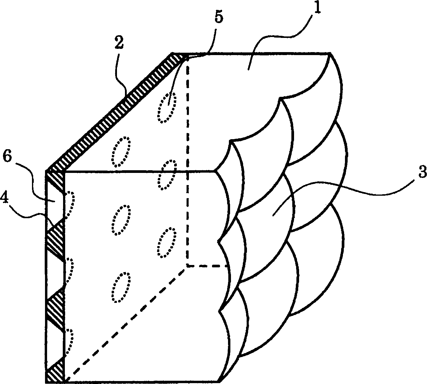
[0081] figure 1 It is an enlarged perspective sectional view of main parts showing an embodiment of the rear projection screen of the present invention. exist figure 1 Among them, the microlens array sheet 1 is a transparent sheet with microlenses 3 formed on one surface. The microlens 3 is a microlens whose surface is formed of a spherical surface, an elliptical surface, an aspheric surface, or the like. It is formed into a shape suitable for various conditions such as usage. The microlens array sheet 1 can be made of transparent polymer materials such as acrylic resin, polycarbonate resin, cycloolefin resin, and polyethylene resin.

[0082] The microlens 3 is formed as a spherical surface, an elliptical surface, or the like with the center of the area divided into squares or rectangles as the center of symmetry. The pitch of the regions divided into squares or rectangles is 100 to 500 μm, typically preferably 150 to 220 μm.

[0083] In addition, the thickness of the m...

Embodiment 2

[0102] FIG. 5 shows an enlarged schematic cross-sectional view of another embodiment of the rear projection screen of the present invention. Figure 5 shows the embodiment with figure 1 The embodiment shown differs in that the pinhole 5 is square or rectangular in shape and the opening 6 is in the shape of a quadrangular truncated pyramid. Functions related to other parts are the same as those in Embodiment 1, and therefore description thereof will be omitted.

[0103] In the embodiment shown in FIG. 5 , the shape of the pinhole 5 is square or rectangular, and the shape of the opening 6 is a quadrangular truncated pyramid, so that the directional light-absorbing sheet 2 can have anisotropy in the vertical direction and the left-right direction. As described above, external light from lighting, windows, etc. is often incident on the screen from the vertical direction and the left and right directions. Due to this structure, various external light can be effectively blocked.

...

Embodiment 3

[0107] Image 6 An enlarged cross-sectional schematic view showing an embodiment of the rear projection screen of the present invention. Image 6 and Figure 4 The difference is that the light-scattering particles 1 are filled in the openings formed on the directional light-absorbing sheet 2 together with a transparent adhesive.

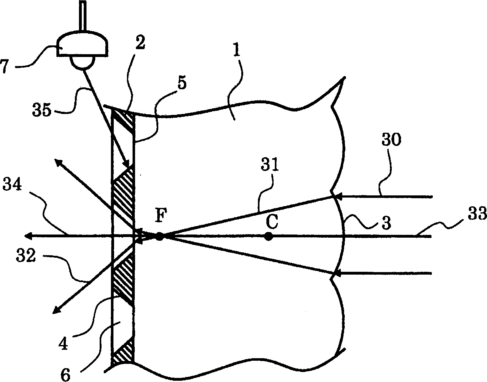
[0108] Such as Figure 4 As shown, by shifting the position of the pinhole 5 outward at the edge of the screen, the light from the projector can be effectively emitted from the screen surface. The radiation distribution is different and therefore the viewing angle dependence is different. That is, the brightness of the image on the screen differs depending on the angle from which the screen is viewed.

[0109] exist Image 6 In this case, even in this case, the variation in the radiation distribution of the light emitted from the screen can be reduced, and the image on the screen can be observed with the same brightness no matter from which angl...


PUM


Abstract

In a screen using a microlens array, it is an object of the present invention to provide a low cost rear projection type screen with favorable contrast achieved by improving effect of blocking external light without reducing the luminance and the view angle characteristics and also to provide a rear projection type screen free from image quality degradation over a prolonged period due to its resistance to dust adhesion. The rear projection type screen has at least a transparent microlens array sheet 1 having a transparent microlens 3 which are arrayed on one surface thereof and which condenses parallel incident light on a focus, and a directional light absorbing sheet 2 having an aperture which transmits light from a specific direction and absorbs other light. The aperture is a pinhole array having an apertured pinhole 5 arrayed near the focus of the microlens 3. The aperture part of the pinhole is shaped into a truncated cone.

Description

technical field [0001] The invention relates to a rear projection screen used in image display devices such as rear projection projection televisions. Background technique [0002] In recent years, the market for rear-projection projection televisions has been expanding as an image display device capable of obtaining a large-screen image at a low price. [0003] The characteristics of the rear projection screen used therein greatly contribute to the brightness, contrast, and viewing angle characteristics of an image projected by a rear projection projection television. Therefore, in order to improve the characteristics of the screen, such as Figure 18 As shown, there is known a lenticular lens type screen, which uses a Fresnel lens sheet 103 to convert the divergent light 105 from the projector into a parallel light 106, and then uses a lenticular lens sheet 102 as a microcylindrical lens array to make the conversion into parallel light The light is concentrated on the gap...

Claims


Application Information

Patent Timeline
Patent Type & Authority Applications(China)
IPC IPC(8): G03B21/60G03B21/62
CPCG03B21/625G03B21/10G03B21/56H04N5/74
Inventor 兵部行远
Owner MIRAIAL CO LTD
Why Eureka
Try Eureka