
Display Element

Inactive Publication Date: 2008-08-28
KONICA MINOLTA INC
View PDF1 Cites 3 Cited by
  • Summary
  • Abstract
  • Description
  • Claims
  • Application Information

AI Technical Summary

Benefits of technology

[0013]According to the present invention, it is possible to provide a display element which is composed of a simple member structure, is drivable at low voltage, exhibits high display contrast and high white display reflectance, and minimizes image mottle.

Problems solved by technology

Specifically, when electronic information includes document information, it is required to watch any of the above viewing means for a relatively long period.
It is common knowledge that light emitting type displays result in problems such as eye fatigue due to flicker, inconvenient portability, limitations in reading posture, necessity to look at still images, or an increase in power consumption.
However, it is difficult to state that due to the following reasons, they exhibit sufficient performance.
Namely, a system employing polarizing plates, such as a reflection type liquid crystal, results in a problem for a white display due to a low reflectance of approximately 40%.
In addition, it is difficulty to state that most methods to produce structuring members are simple and easy.
Further, polymer dispersion type liquid crystals require high voltage and the contrast of the resulting images is insufficient due to utilizing the difference in refractive indices between organic compounds.
Still further, polymer network type liquid crystals result in problems such as application of high voltage and requirement of complicated TFT circuitry to enhance memory capability.
Yet further, display elements employing electrophoresis require high voltage of at least 10 V and tend to suffer insufficient durability due to aggregation of electrophoretic particles.
Further, electrochromic display elements, though being drivable at a low voltage of at most 3 V, result in insufficient color quality of black and common colors (namely yellow, magenta, cyan, blue, and red) and tend to result in problems such that, in order to secure memory capability, the display cell requires a complicated film structure such as vapor deposition film.
In conventional technologies, when white pigments were dispersed in an electrolyte, the resulting dispersion stability of the white pigments was insufficient, whereby white display reflectance fluctuated over an elapse of time.
As a result, problems were found in which white display reflectance was not sufficient, leading to further investigation.
However, it was found that non-uniform thickness of the white scattering layer resulted, depending on the preparation method of the relatively thick white scattering layer, whereby image mottle is formed.

Method used


Image

  • Display Element
  • Display Element
  • Display Element

Examples


examples

[0110]The present invention will now be described with reference to examples, but is not limited thereto. In examples, “parts” and “%” are parts by weight and % by weight, respectively, unless otherwise specified.

>

(Preparation of Display Element 1)

(Preparation of Electrolyte 1)

[0111]Added to and completely dissolved in 2.5 g of dimethyl sulfoxide were 90 mg of sodium iodide and 75 mg of silver iodide. Thereafter, added was 150 mg of polyvinylpyrrolidone (of an average molecular weight of 15,000), and the resulting mixture was heated at 120° C. while stirring, whereby Electrolyte 1 was prepared.

(Preparation of Transparent Electrode)

[0112]A tin-doped indium oxide film (also referred to as an ITO film) of a pitch of 145 μm and an electrode width of 130 μm was formed on a glass substrate of a thickness of 1.5 mm and a width of 2 cm×4 cm, employing known method, whereby a transparent electrode (Electrode 1) was prepared.

(Preparation of Metal Electrode)

[0113]A silver-palladium electrode (...


PUM


Abstract

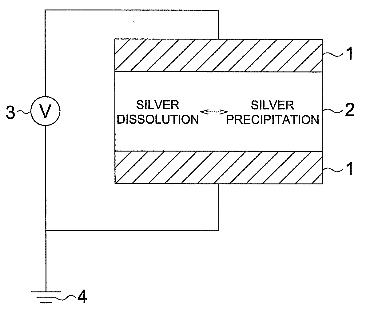
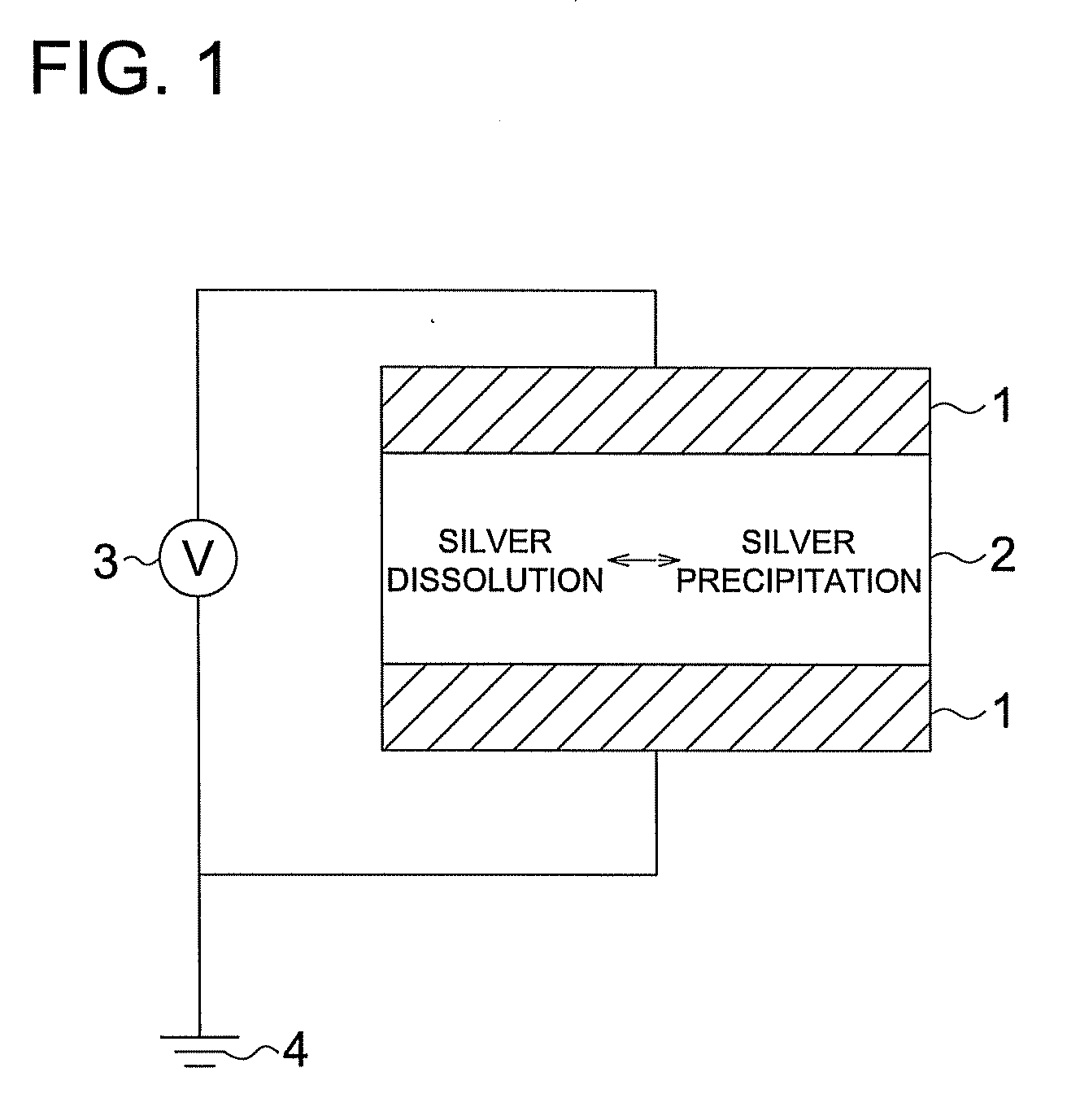
This invention provides a display element that has a simple member construction, can be driven at a low voltage, has high display contrast and white display reflectance, and has reduced unevenness in images. The display element comprises opposed electrodes and an electrolyte containing silver or a compound containing silver in its chemical structure and a porous white scattered material provided between the opposed electrodes. The opposed electrodes are driven and operated so that silver is dissolved and precipitated. The display element is characterized in that the porous white scattered material is formed by coating an intimate water mixture containing titanium oxide, an aqueous polymer for binding the titanium oxide, and a thickening polysaccharide onto at least one of the opposed electrodes, and then drying the coating.

Description

TECHNICAL FIELD[0001]The present invention relates to an electrochromic display element utilizing silver dissolution and deposition.BACKGROUND[0002]In recent years, along with enhancement of the operation rate of personal computers, and popularization of network infrastructure, as well as an increase in capacity of data storage and a decrease in its cost, occasions have increasingly occurred in which pieces of information such as documents and images, which have been provided in the form of paper printed matter, are received as simpler electronic information and viewed as received electronic information.[0003]As viewing means for such electronic information, mainly employed are those of light emitting types such as conventional liquid crystal displays and CRTs or recent organic electroluminescence displays. Specifically, when electronic information includes document information, it is required to watch any of the above viewing means for a relatively long period. However, it is hardl...

Claims


Application Information

Patent Timeline
IPC IPC(8): G02F1/155
CPCG02F1/1525G02F1/1508
Inventor KOKEGUCHI, NORIYUKI
Owner KONICA MINOLTA INC
Learn More