Clutch assembly in a gearbox comprising two axially and radially adjoining clutches

A clutch device, clutch technology, applied in clutches, friction clutches, fluid-driven clutches, etc., can solve problems such as associated defects

Inactive Publication Date: 2006-12-06
ZF FRIEDRICHSHAFEN AG
View PDF1 Cites 9 Cited by
  • Summary
  • Abstract
  • Description
  • Claims
  • Application Information

AI Technical Summary

Problems solved by technology

Although this solution is technologically more economical, it has the disadvantage that the axial position of the outer disc pack depends on the position of the inner disc pack and therefore cannot be optimally selected in terms of construction space

Method used


Image

  • Clutch assembly in a gearbox comprising two axially and radially adjoining clutches
  • Clutch assembly in a gearbox comprising two axially and radially adjoining clutches
  • Clutch assembly in a gearbox comprising two axially and radially adjoining clutches

Examples


Embodiment Construction

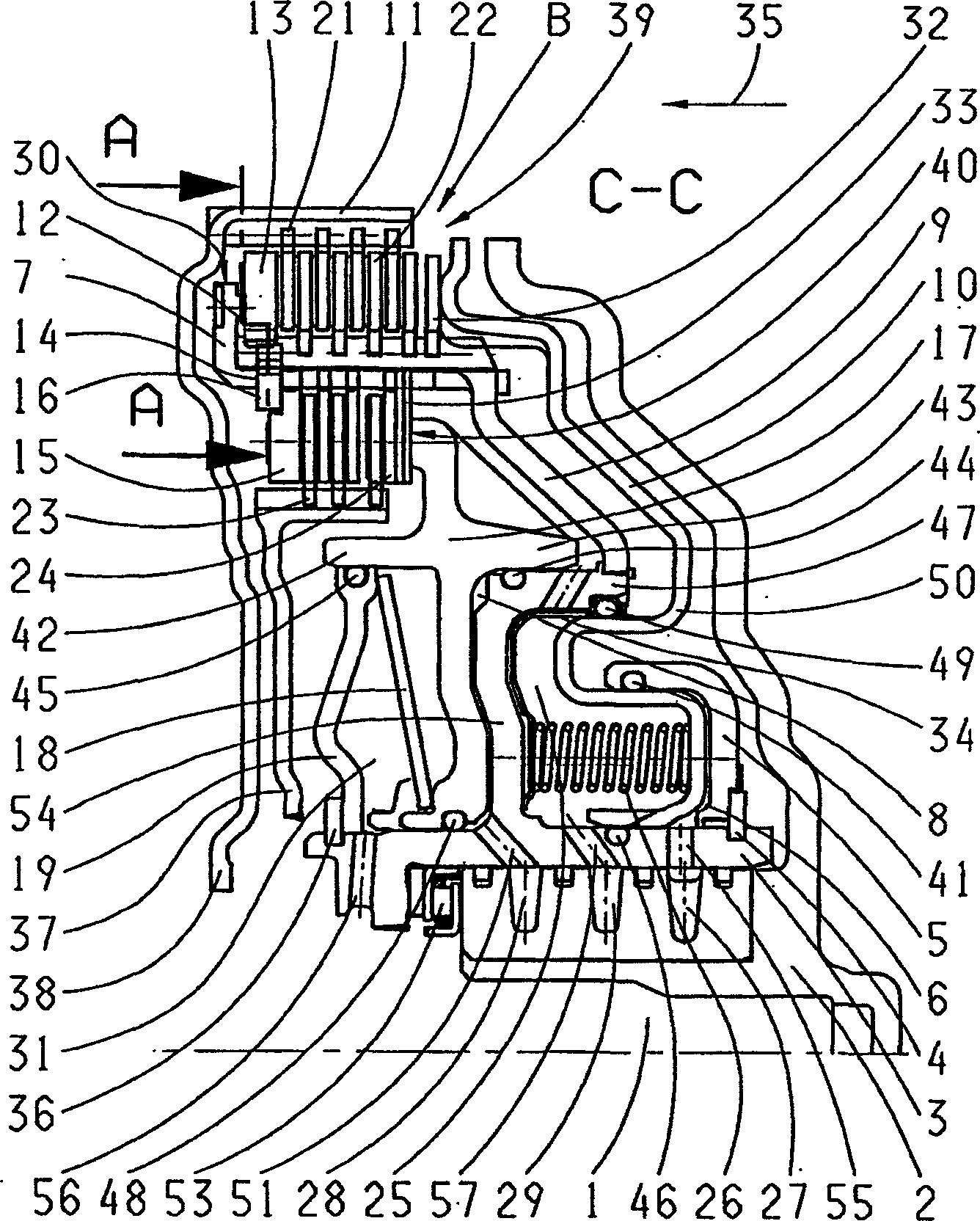
[0027] therefore figure 1 A transmission is shown in cross-section in the region of two multi-disk clutches B and E, which are arranged radially and axially directly adjacent in a transmission housing 2 . The design of the clutch arrangement selected here provides that the clutch E is arranged radially directly below the outer clutch B.

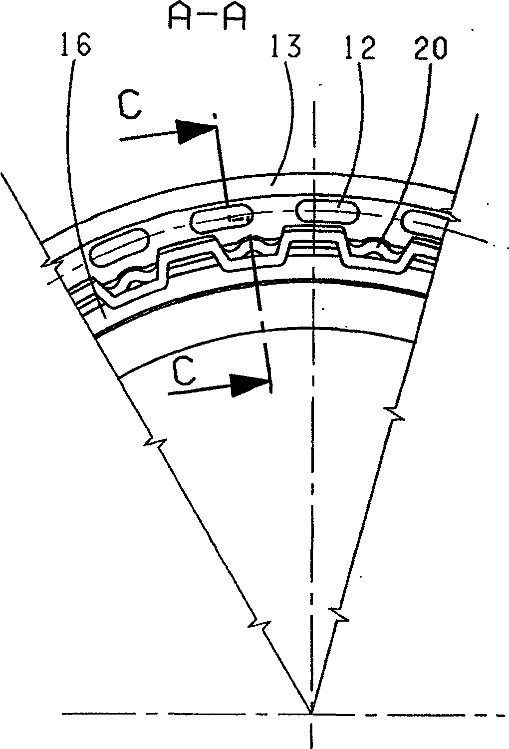
[0028] figure 2 show figure 1 A cross-sectional view of the region A-A in figure 1 Looking in the direction indicated by the two arrows. exist figure 2 The truncation plane C-C shown in the figure 1 Side view of a structural component within the area of ​​the cut line selected in .

[0029] The two disk packs 39, 40, the corresponding outer and inner disk carriers 37, 38 as well as the clutch actuating pistons 10, 17 of the pressure-medium-actuated actuating servo are among the core components of this clutch arrangement, by means of which the Make both clutches close in the same direction of actuation. In this clutch device, the str...


PUM


Abstract

The invention relates to a clutch assembly in a gearbox, in particular an automatic gearbox or automated manual gearbox of the double-clutch type, comprising two axially and radially adjoining multi-plate clutches (B, E). The inner plates (23) of the radial inner clutch (E) are located on an inner clutch-plate carrier (37) and the outer plates (21) of the radial outer clutch (B) are located on an outer clutch-plate carrier (38), whilst the inner plates (22) of the radial outer clutch (B) and the outer plates (24) of the radial inner clutch (E) are located on a common clutch-plate carrier (9). In addition, the plates (23, 24) of the radial inner plate stack (40) are supported axially against a circlip (16) that is fixed to the common clutch-plate carrier (9). The aim of the invention is to provide a space-saving, cost-effective clutch assembly. To achieve this, the plates (21, 22) of the radial outer plate stack (39) can be pressed in an axial direction against a bearing section (7) of the common clutch-plate carrier (9), said section consisting of an end piece of the common clutch-plate carrier (9) that faces radially outwards.

Description

technical field [0001] The invention relates to a clutch arrangement in a transmission, in particular an automatic transmission or an automatic shift transmission, according to the preamble of claim 1 . Background technique [0002] There are various known examples of clutch structures and their actuation in automatic transmissions. For example, US Pat. No. 6,120,410 shows a clutch device in an automatic transmission, in which a component with a substantially cup-shaped cross section forms the outer friction lining carrier. The inner and outer friction plates of two plate clutches arranged axially side by side and arranged at the same radial height are formed radially inside this outer friction plate carrier, each having an actuating piston for actuating the two clutches. A piston-cylinder arrangement, and a pressure balancing chamber for dynamic pressure balancing in relation to the actuating force of the actuating piston. [0003] Furthermore, a clutch device in an autom...

Claims


Application Information

Patent Timeline
Patent Type & Authority Applications(China)
IPC IPC(8): F16D25/10F16D25/0638F16D13/68F16D13/52F16D13/64
CPCF16D25/0638F16D2021/0661F16D25/10F16D13/648F16D13/64F16D25/06F16D25/00
Inventor P·蒂斯勒J·道森德
Owner ZF FRIEDRICHSHAFEN AG
Why Eureka
Try Eureka