

Gas turbine generator
A gas turbine generator and generator technology, applied in electromechanical devices, electrical components, electric components, etc., can solve problems such as exhaust gas cannot be used, generator cannot be moved, energy waste, etc., to save resources, reduce input costs, The effect of simple installation
- Summary
- Abstract
- Description
- Claims
- Application Information
AI Technical Summary
Problems solved by technology
Method used
Image

Examples
Embodiment Construction
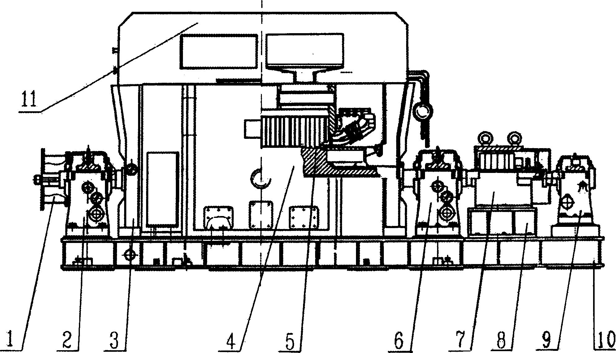
[0016] Below in conjunction with accompanying drawing, the present invention will be further described: as figure 1 As shown, the gas turbine generator adopts an integral box structure, the generator is placed in the main chassis, the main chassis is provided with an end cover 3, the generator adopts a double-supported brushless excitation structure, the floor 10 is an integral floor, and the floor 10 On both sides, there are top plates and lifting bolts for adjusting the position of the center line of the generator and the left and right positions, and there are also side plates for axial fixing. The end cover and the bottom cover are all welded steel plates. There is a generator lead wire outlet box on the side, and an electric heater for heating and dehumidification of the generator is installed on the bottom cover. A windshield 1 is provided on the side of the steam end bearing 2 of the generator, and the exciter 7 is directly set on the excitation end bearing 6 of the gen...
PUM
 Abstract
Description
Claims
Application Information