

Renewable energy feed-back parallel network circuit and its control device
A renewable energy and circuit technology, which is applied in circuit devices, AC network circuits, output power conversion devices, etc. The effect of high efficiency, high power factor and reliable operation
- Summary
- Abstract
- Description
- Claims
- Application Information
AI Technical Summary
Problems solved by technology
Method used
Image

Examples
Embodiment 1
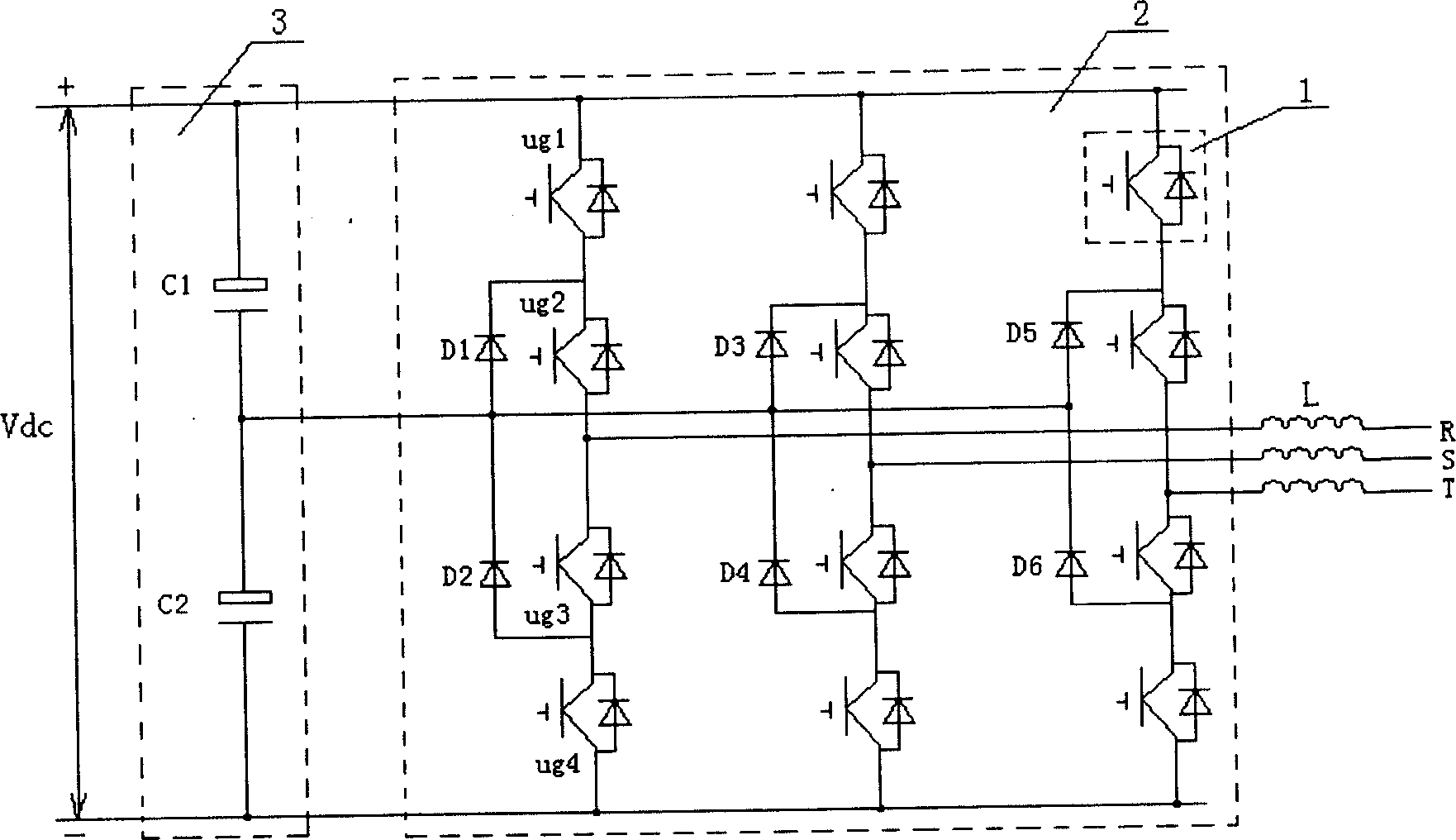
[0021] Such as figure 1 Shown is a grid-connected circuit diagram of a renewable energy feedback grid-connected diode clamped three-level circuit. Its specific structure is: an absorption filter circuit 3 composed of C1 and C2 in series is connected in parallel between the positive and negative bus bars of the external input DC power supply Vdc, and a group of three-level circuits are connected in parallel between the positive and negative bus bars behind the absorption filter circuit 3 2. After the midpoint of the clamping diode of each phase of the three-level circuit 2 is connected, it is connected to the middle of the filter absorption circuit 3, and the midpoint of the series connection of the power device 1 of each phase passes through a current sharing inductance L and the output AC R, S, T are connected.
Embodiment 2
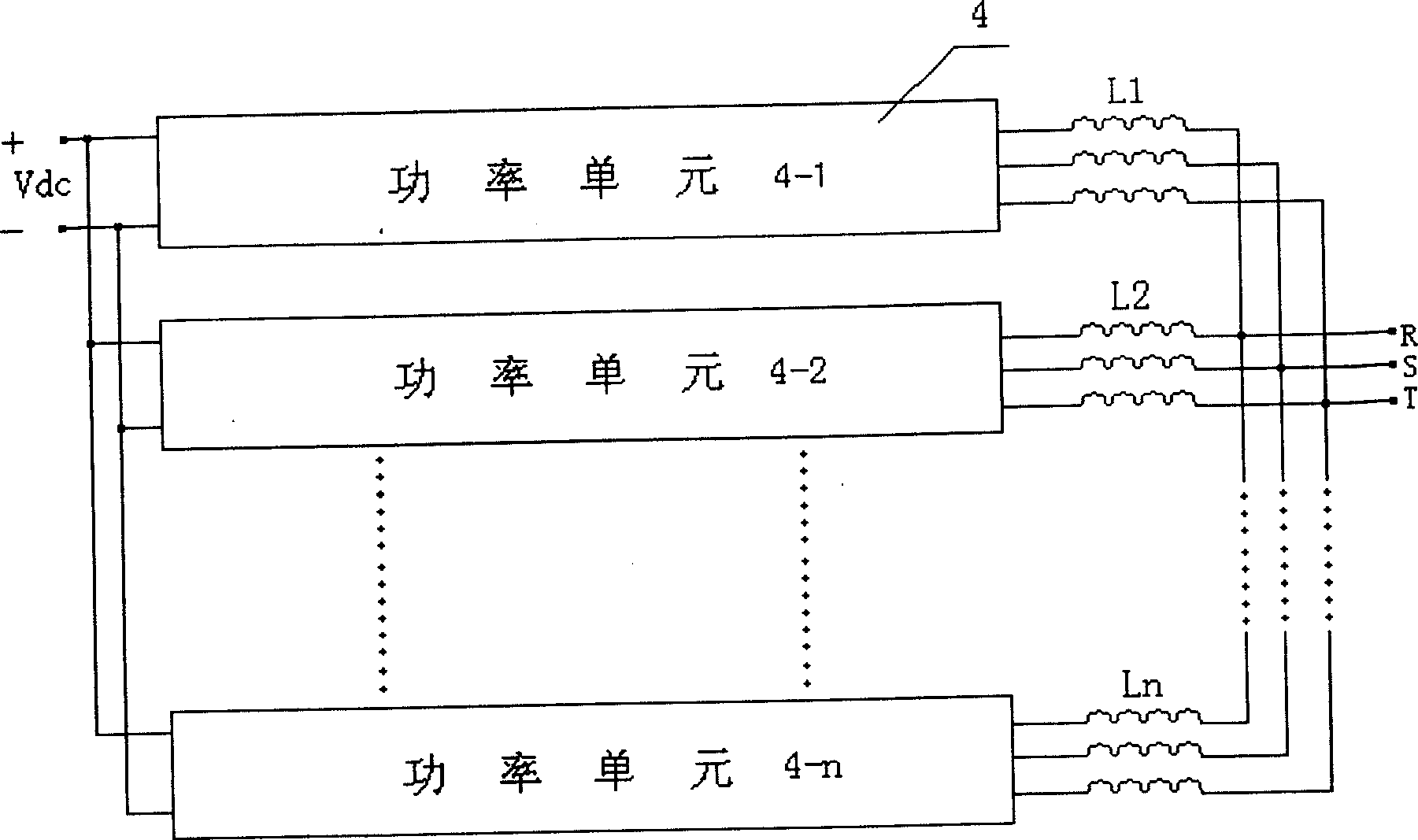
[0023] Such as figure 2 As shown, it is a renewable energy feedback grid-connected circuit diagram of a three-level circuit multi-unit parallel connection when large capacity is required. Its specific structure is as follows: the external input DC power supply Vdc is delivered to the power unit 4-1, and the power unit 4-1 passes through the current equalizing inductor L1 to output the alternating current R, S, T; similarly, the external input DC power supply Vdc is delivered to the power unit 4-2 , the power unit 4-2 passes through the current sharing inductance L2 to the output AC R, S, T; there are 1 input DC power supply, n power units, and n current sharing inductances to form n identical power circuits, all of which are identical to the final Output alternating current R, S, T phase connection. The external input of these n identical power circuits is the same direct current Vdc; the n circuits are respectively connected in parallel and then connected to the output alte...
Embodiment 3
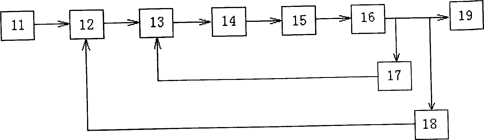
[0025] Such as image 3 Shown is the control device of the renewable energy feedback grid-connected circuit of the present invention. Its specific structure is: the bus voltage given signal 11 is transmitted to the voltage regulator 12, the voltage regulator 12 transmits the output signal to the current regulator 13, the current regulator 13 transmits the output signal to the PWM signal generating circuit 14, and the PWM signal is generated The circuit 14 transmits the PWM wave signal to the renewable energy feedback grid-connected circuit 15, and the renewable energy feedback grid-connected circuit 15 converts direct current into alternating current and directly feeds back to the grid 19 through the current equalization and circulation suppression circuit 16. A current sampling circuit 17 and a voltage sampling and synchronous signal generating circuit 18 are arranged between the circuit 16 and the grid 19. The current sampling circuit 17 feeds back the current sampling signa...
PUM
 Abstract
Description
Claims
Application Information