Laser projection display device based on optical fibre laser

A fiber laser and display device technology, which is applied in the direction of image reproducer and picture reproducer of projection device, can solve the problems of hindering commercialization, civilianization, increasing the volume of laser TV, and high cost, and achieves the promotion of commercialization and production. Civilization, good output beam quality and high output power

Inactive Publication Date: 2006-12-27
NORTHWEST UNIV(CN)
View PDF0 Cites 3 Cited by
  • Summary
  • Abstract
  • Description
  • Claims
  • Application Information

AI Technical Summary

Problems solved by technology

At present, laser TV is still in the stage of experimental research, and the main factors hindering its commercialization and civilian use are: (1) the primary color laser source is bulky and expensive; (2) the high-speed scanning device is technically difficult
At present, the primary color light source of laser TV is mainly obtained through the following two methods: (1) using beam expansion technology to obtain uniform light projection, but there is serious interference noise in the picture; (2) using rapidly developing all-solid-state lasers as red and green , blue primary color generation device, the current experimental research on laser TV mostly uses this method to obtain the primary color light source, combined with the advantages of high power and high beam quality of solid-state lasers, it can greatly improve the resolution and stability of laser color video images , clarity, brightness and other performances, but the all-solid-state lasers used in laser TVs are bulky and require water-cooling devices, and the cost is high. Combined with the high-speed scanning system, the volume is also relatively large, etc. These inherent defects will increase the volume of laser TVs And increase its price, thus seriously hindering the commercialization and civilian use of laser TV

Method used


Image

  • Laser projection display device based on optical fibre laser
  • Laser projection display device based on optical fibre laser

Examples


Embodiment Construction

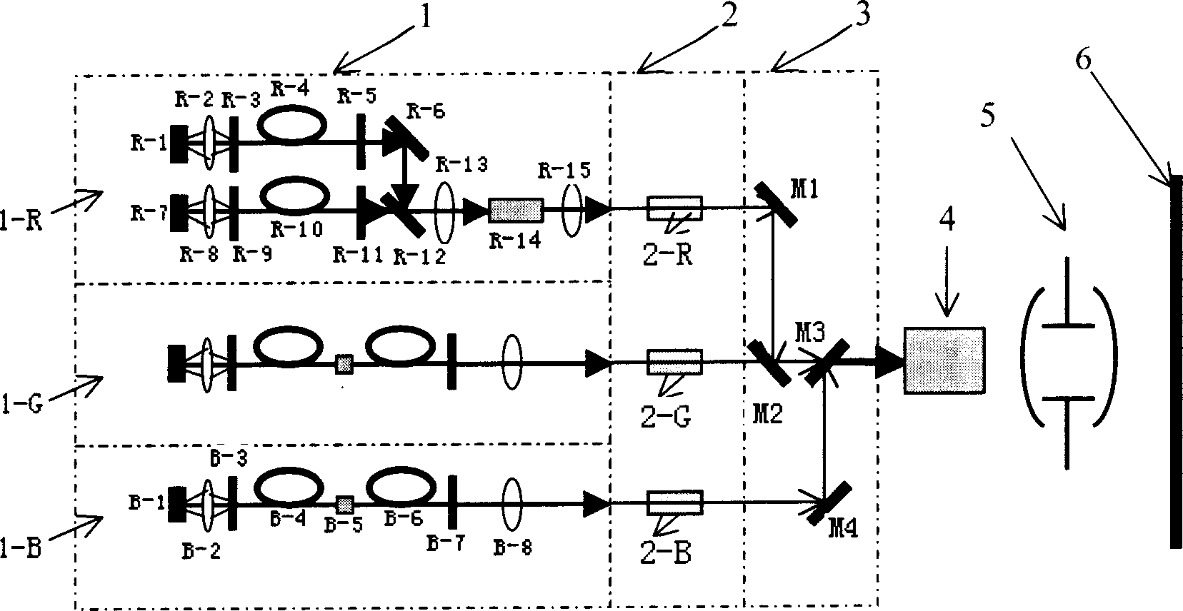
[0018] refer to figure 1 As shown, the red optical modulator 2-R is installed behind the red optical fiber laser 1-R, and the red reflector M1 is installed behind the red optical modulator 2-R. The three are in the same collimated red light path, and the red light reflection The mirror M1 is placed at an inclination angle of 135°; the green optical modulator 2-G is installed behind the green optical fiber laser 1-G, and the front dichroic film M2 and the rear dichromatic film M3 are arranged in sequence behind the green optical modulator 2-G. They are in the same collimated green light path, and the light path is parallel to the lower part of the above-mentioned red light path, M2 is arranged in parallel directly below the red light reflector M1 at an inclination angle of 135°, and the rear dichroic film M3 is placed at an inclination angle of 45°; the blue light A blue light optical modulator 2-B is set behind the fiber laser 1-B, and a blue light reflector M4 is set behind t...


PUM


Abstract

The disclosed laser projection display device based on fiber laser comprises: from front to back, a fiber laser device to generate three primary colors, a light path modulation device, a beam synthesis device, a scanner, a projection objective, and a display screen, wherein the laser device comprises a red fiber laser as outside added frequency structure, a green and blue fiber laser both as inner double frequency structure. This invention improves laser display quality greatly with low cost and long lifetime.

Description

technical field [0001] The invention belongs to the field of laser video display, which uses fiber lasers as the laser light source in laser video display, which can greatly improve the performance of laser projection display, such as clarity, resolution and brightness. Laser projection display device with fiber laser. Background technique [0002] Since the 1990s, with the continuous development of high and new technologies, TV display technology has also been constantly introducing new ones. Various color TV display technologies have been researched internationally, such as LCD TV display technology, rear projection TV display technology, plasma TV display technology, etc. TV display technology and more. With the development of all-solid-state laser technology, especially the appearance of red, green, and blue primary-color lasers that can produce high power and high beam quality, the development of laser color TV display technology has been promoted. Using the advantage...

Claims


Application Information

Patent Timeline
Patent Type & Authority Applications(China)
IPC IPC(8): H04N9/31
Inventor 白晋涛
Owner NORTHWEST UNIV(CN)
Why Eureka
Try Eureka