Liquid storing device for storing refrigrant in device

A liquid storage device and body technology, which is applied in the welding structure field of the liquid outlet pipe of the air-conditioning liquid storage device, can solve the problems of affecting the quality of the air-conditioning liquid storage device, high energy consumption, cracks, etc., and achieves simple structure and improved welding Process, the effect of reducing welding energy consumption

Active Publication Date: 2007-01-03
ZHEJIANG SANHUA INTELLIGENT CONTROLS CO LTD
View PDF1 Cites 8 Cited by
  • Summary
  • Abstract
  • Description
  • Claims
  • Application Information

AI Technical Summary

Problems solved by technology

This kind of air-conditioning liquid reservoir is mostly made of stamped iron body in actual production. , due to the poor plasticity of iron, there are often processing defects such as cracks, so that it is difficult to make up for such defects after high-quality welding, which in turn affects the quality of the entire air-conditioning reservoir; It is still difficult to avoid such defects when flaring in order to form the above-mentioned steps or cooperate with the tubular flange
In addition, due to the particularity of the structure, the welding quality of the above-mentioned inner iron pipe and outer copper pipe also depends on high-quality welding technology. Big

Method used


Image

  • Liquid storing device for storing refrigrant in device
  • Liquid storing device for storing refrigrant in device
  • Liquid storing device for storing refrigrant in device

Examples


Embodiment Construction

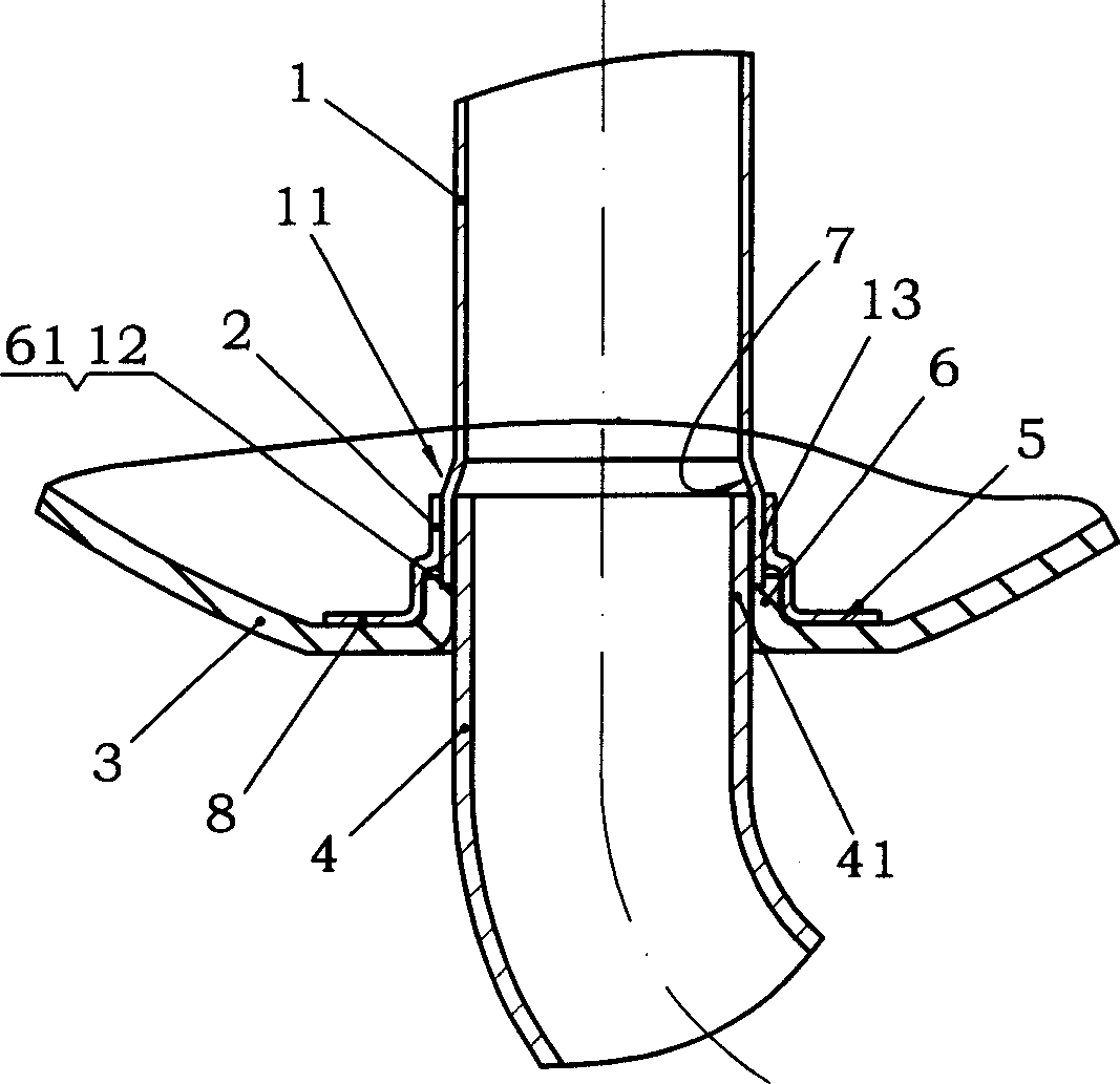
[0033] Such as image 3 As shown, a tubular flange 6 extending axially toward the inside of the body is provided at the center of the lower end of the body 3 , and a step 61 is provided at the upper end of the tubular flange 6 , and an iron thin-walled sleeve is placed on the tubular flange 6 Adapter seat 2, and its welding edge 8 is welded on the inner plane 5 of the body by bump welding, and the inner iron pipe 1 that has been flared is spot-welded on the adapter seat 2 through the outer wall 13 of its flared part 11 on the inner wall of the inner iron pipe, so as to realize the fixing of the inner iron pipe, and there is a step 7 near the tubular flange 6; the adapter seat 2 is set on the tubular flange 6 and welded with the body, so that the lower end of the inner iron pipe 12 interferes with the step 61 at the upper end of the tubular flange 6; the upper part 41 of the outer copper tube is inserted along the tubular flange, abuts against the step 7 of the flared part and ...


PUM


Abstract

This invention is liquid storage inside of machine that is used for storing refrigerants. The existing liquid discharge wielding structure of liquid storage is: tubular flanging is set at underside of the machine. Inner iron pipe and outer copper pipe are wielded at the tubular flanging. It may cause defects such as cracking before wielding. This invention is to fix the said inner iron pipe on a switching seat. The switching seating is set on the said tubular flanging and wielded with the underside of machine to form step at the position of tubular flanging. The said copper pipe contacts with the said step and is wielded with the underside of machine.

Description

technical field [0001] The invention relates to a welding structure of a liquid storage container, in particular to a welding structure of a liquid outlet pipe of an air-conditioning liquid storage device. Background technique [0002] The air conditioning liquid reservoir is an important part of the air conditioning system, such as figure 1 As shown, it is installed in front of the compressor when used; its working principle is as follows figure 2 As shown, the refrigerant from the evaporator enters the accumulator from the upper end A (inlet end), splits through the screen seat D, and flows from the periphery of the vessel to the bottom of the accumulator, and the gaseous refrigerant enters the upper end B of the outlet pipe (inner end ), flows out through the outlet port C (outer end), and enters the compressor, while the liquid refrigerant stays at the bottom of the accumulator; it mainly has the following functions and uses: [0003] 1. The ga...

Claims


Application Information

Patent Timeline
Patent Type & Authority Applications(China)
IPC IPC(8): F25B43/00
Inventor 陈枫吕小丹石峰张志翔
Owner ZHEJIANG SANHUA INTELLIGENT CONTROLS CO LTD
Why Eureka
Try Eureka