Bearing device for turbocharger

A technology of turbocharger and bearing device, which is applied in bearing assembly, lubrication of turbine/propulsion device, bearing of rotary motion, etc., can solve the problems of increased processing cost, trouble in production, insufficient rotation and fixation, etc.

Inactive Publication Date: 2007-01-03
JTEKT CORP
View PDF0 Cites 49 Cited by
  • Summary
  • Abstract
  • Description
  • Claims
  • Application Information

AI Technical Summary

Problems solved by technology

[0004] However, this bearing device for a turbocharger is formed in a complicated shape: the steel outer ring is formed in the shape of the inner side of the housing, and has a spring receiving portion, an oil hole, etc.
Therefore, the production is very laborious, thereby increasing the processing cost
In addition, the rotation of the outer ring relative to the housing is not sufficiently fixed, so that the bearing cannot be properly arranged in the housing, and the oil hole may be misaligned.

Method used


Image

  • Bearing device for turbocharger
  • Bearing device for turbocharger
  • Bearing device for turbocharger

Examples


Embodiment Construction

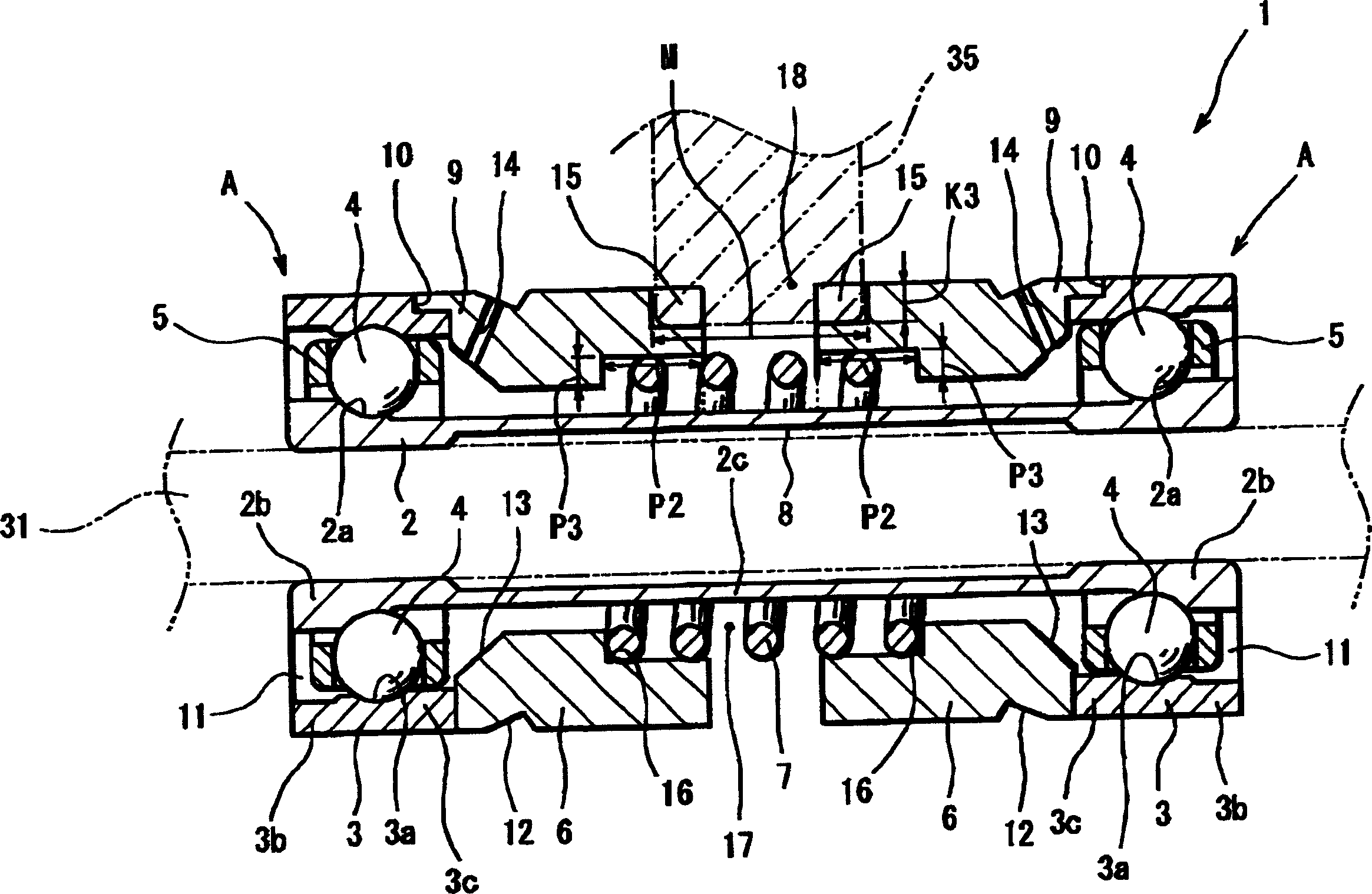
[0016] Hereinafter, embodiments of the present invention will be described with reference to the drawings.

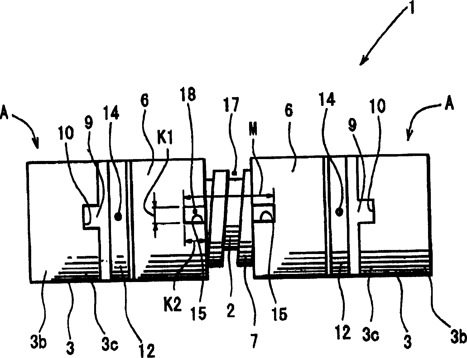
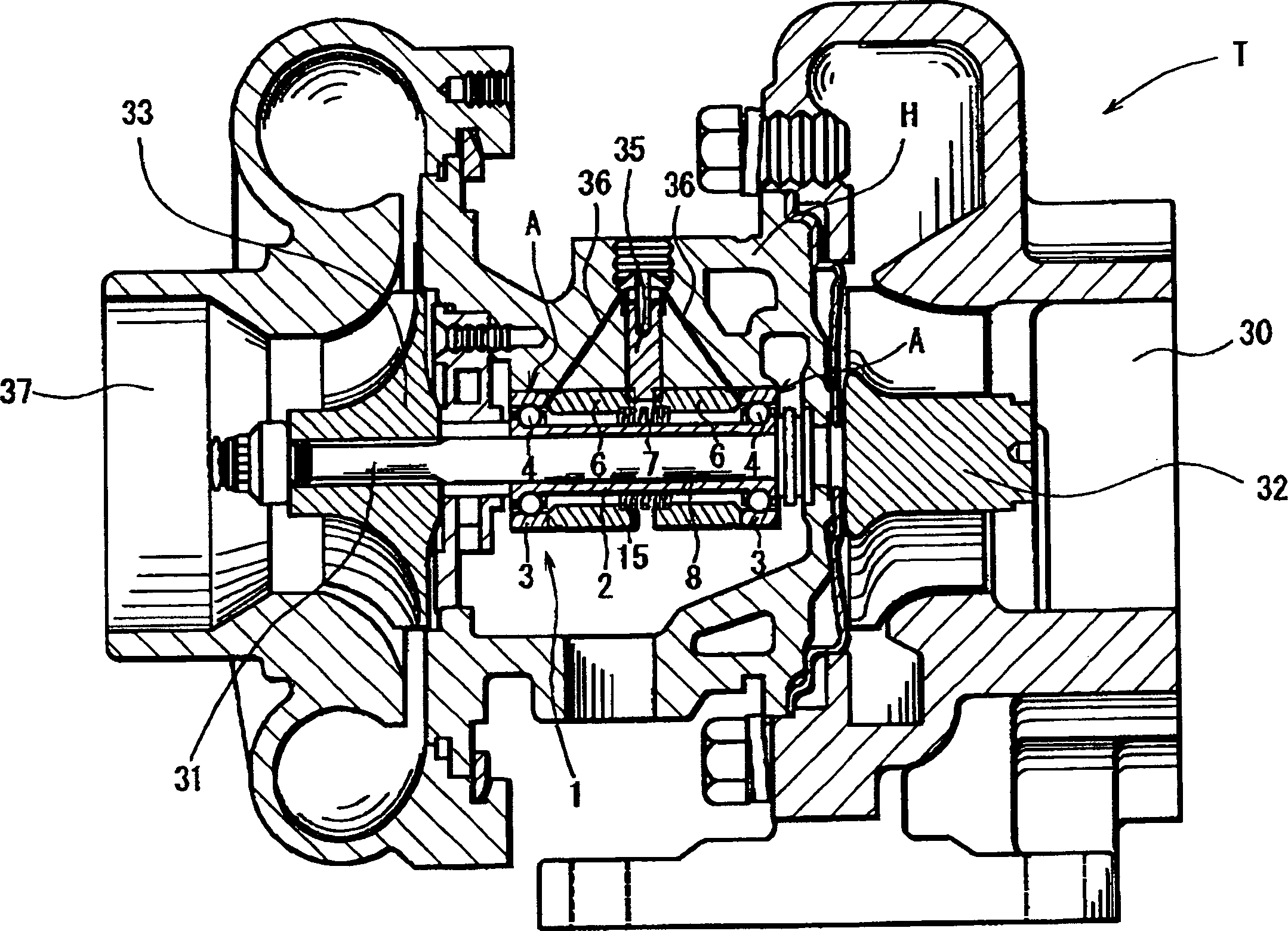
[0017] figure 1 It is a sectional view showing the first embodiment of the turbocharger bearing device 1 according to the present invention. figure 2 is its floor plan. image 3 A schematic diagram showing a turbocharger T incorporating the turbocharger bearing device 1 is shown. The turbocharger T is fixed on one end of the rotating shaft 31 ( image 3 The turbine 32 on the right side) rotates. The rotation of the rotating shaft 31 is transmitted to the other end fixed on the rotating shaft 31 ( image 3 The impeller 33 on the left side of the left side), so that the air sucked in the suction line 37 is compressed by the impeller 33 . As a result, the compressed air is sent into the cylinder chamber of the engine together with fuel such as gasoline and light oil. The rotary shaft 31 of such a turbocharger T rotates at a high speed of tens of thousands to hundred...


PUM


Abstract

A turbocharger bearing assembly is disposed in a housing for rotatably supporting an intermediate portion of a rotary shaft of a turbocharger. A pair of outer rings formed with outer raceways are mounted to opposite ends of a substantially cylindrical inner ring formed with inner raceways, thereby constituting a bearing unit including two angular bearings. Thus, the number of assembly steps is reduced to facilitate an assembly work. A pair of sleeves are inserted in a gap defined between the outer rings. The sleeve is formed with an engaging portion on an outer periphery thereof for restricting its rotation relative to the housing and the outer ring. This makes it easy to position the bearing in the housing.

Description

technical field [0001] The present invention relates to a bearing device for freely rotatably supporting a rotary shaft of an automobile turbocharger. Background technique [0002] Recently, due to the demand for energy-efficient vehicles with small displacement, the number of vehicles equipped with turbochargers is gradually increasing. This turbocharger has a rolling bearing (hereinafter referred to as a bearing) that rotatably supports its rotating shaft inside a casing. Such bearings are used in very harsh environments: ultra-high-speed rotation, extreme acceleration and deceleration, ultra-high temperature, and good rotational accuracy. Therefore, it is necessary to apply an appropriate preload to the bearing, so it is suitable to apply a constant pressure preload to the bearing. To apply the constant-pressure preload, a washer and a preload-applying spring are mounted between two bearings each having an inner ring and an outer ring. In this case, assembly man-hours i...

Claims


Application Information

Patent Timeline
Patent Type & Authority Applications(China)
IPC IPC(8): F16C25/08F16C19/18F16C33/58F16C33/80F02B39/00F01D25/16F02C7/06F16C33/60F16C33/62
CPCF16C35/077F02C7/06F16C2360/24F16C25/083F16C27/04F05D2220/40F01D25/16F16C19/184F16C35/067F16C2226/50
Inventor 梅川贵弘
Owner JTEKT CORP
Why Eureka
Try Eureka