Dc-Dc converter

A technology of DC-DC converters, applied in the field of DC-DC converters, can solve the problems of increased switching loss and inability to obtain sufficient performance, and achieve the effects of eliminating the decline in conversion efficiency, easy design, and preventing DC offset

Inactive Publication Date: 2007-01-03
HONDA MOTOR CO LTD
View PDF1 Cites 9 Cited by
  • Summary
  • Abstract
  • Description
  • Claims
  • Application Information

AI Technical Summary

Problems solved by technology

When a deviation occurs between the ON / OFF drive frequency of the pair of switch units 2-1, 2-2 and the resonance frequency of the resonance circuit 3 due to this deviation or change, switching loss increases and sufficient performance cannot be obtained.

Method used


Image

  • Dc-Dc converter
  • Dc-Dc converter
  • Dc-Dc converter

Examples


Embodiment Construction

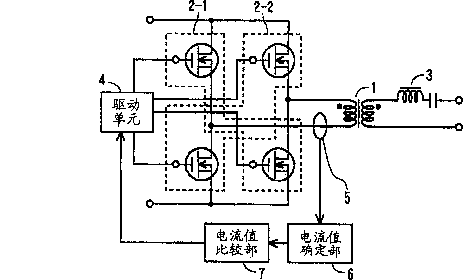
[0030] Hereinafter, the present invention will be described with reference to the drawings. figure 1 It is a circuit diagram showing the principle of the DC-DC converter of the present invention. Hereinafter, the same or equivalent parts as in FIG. 4 are denoted by the same symbols. figure 1 The difference from FIG. 4 is that it has a resonance current detection unit that detects a resonance current generated by the operation of the resonance circuit 3 , and feeds back the resonance current value detected by this unit to the drive unit 4 . The resonant current detection unit is composed of the following parts: the resonant current detection current transformer 5, which is arranged, for example, on the line through which the resonant current on the primary side of the transformer 1 flows; determination; and a current value comparison section 7 which compares the determined resonance current value with a threshold value and feeds back the result to the drive unit 4 .

[0031...


PUM


Abstract

The present invention provides a DC-DC converter capable of eliminating the drop in conversion efficiency that may be caused by the saturation of the voltage conversion transformer, realizing miniaturization of the voltage conversion transformer, and suppressing switching loss to improve conversion efficiency. An LC resonant circuit (3) is inserted on the secondary side of the transformer (1). When a pair of switch units (2-1, 2-2) are alternately turned on / off using a drive unit (4), an output is obtained on a secondary side through a transformer (1). The current detecting current transformer (5), current value determining unit (6) and current value comparing unit (7) detect the difference between half periods of the resonance current value generated by the operation of the LC resonance circuit (3). Based on the detection result, the drive unit (4) automatically adjusts the on-duty ratios of the switch units (2-1, 2-2) so that the resonance current values ​​in each half cycle are consistent.

Description

technical field [0001] The present invention relates to a DC-DC converter, and more particularly to a DC-DC converter capable of suppressing magnetic saturation of a transformer for voltage conversion, realizing miniaturization of the transformer, and suppressing switching loss to improve conversion efficiency. Background technique [0002] The DC-DC converter of the current resonance method has a resonant circuit connected in series with the switching unit, and the switching unit is turned on / off at the resonant frequency of the resonant circuit. FIG. 4 is a diagram showing the principle of a DC-DC converter. On the primary side of the transformer 1, a pair of switching units 2-1, 2-2 constituted by, for example, a bridge structure of four switching elements is provided, and a resonant circuit 3 is provided on the secondary side. The resonance circuit 3 is composed of a resonance choke coil (reactor) and a resonance capacitor. In addition, rectification and smoothing unit...

Claims


Application Information

Patent Timeline
Patent Type & Authority Applications(China)
IPC IPC(8): H02M3/28H02M1/10H02M3/335
CPCH02M1/10Y02B70/1475H02M7/5387Y02B70/1441Y02B70/1433H02M1/40H02M3/33592Y02B70/10H02M3/28
Inventor 江口博之清水元寿
Owner HONDA MOTOR CO LTD
Why Eureka
Try Eureka