CPU radiator for computer host machine

A computer and heat sink technology, applied in the field of computers, can solve the problems of noise fluctuations, etc., and achieve the effect of small size and low speed

Inactive Publication Date: 2007-01-10
TSINGHUA TONGFANG CO LTD
View PDF0 Cites 2 Cited by
  • Summary
  • Abstract
  • Description
  • Claims
  • Application Information

AI Technical Summary

Problems solved by technology

After adopting the wind speed control technology on the motherboard, although the speed and noise of the fan can be appropriately reduced, as the operating program and the ambient temperature change, the speed of the fan will fluctuate from high to low, and the noise will also fluctuate accordingly.
Even in the state of no operation in the windows operating system, the fan noise of the host system is still about 35dBA

Method used


Image

  • CPU radiator for computer host machine
  • CPU radiator for computer host machine

Examples


Embodiment Construction

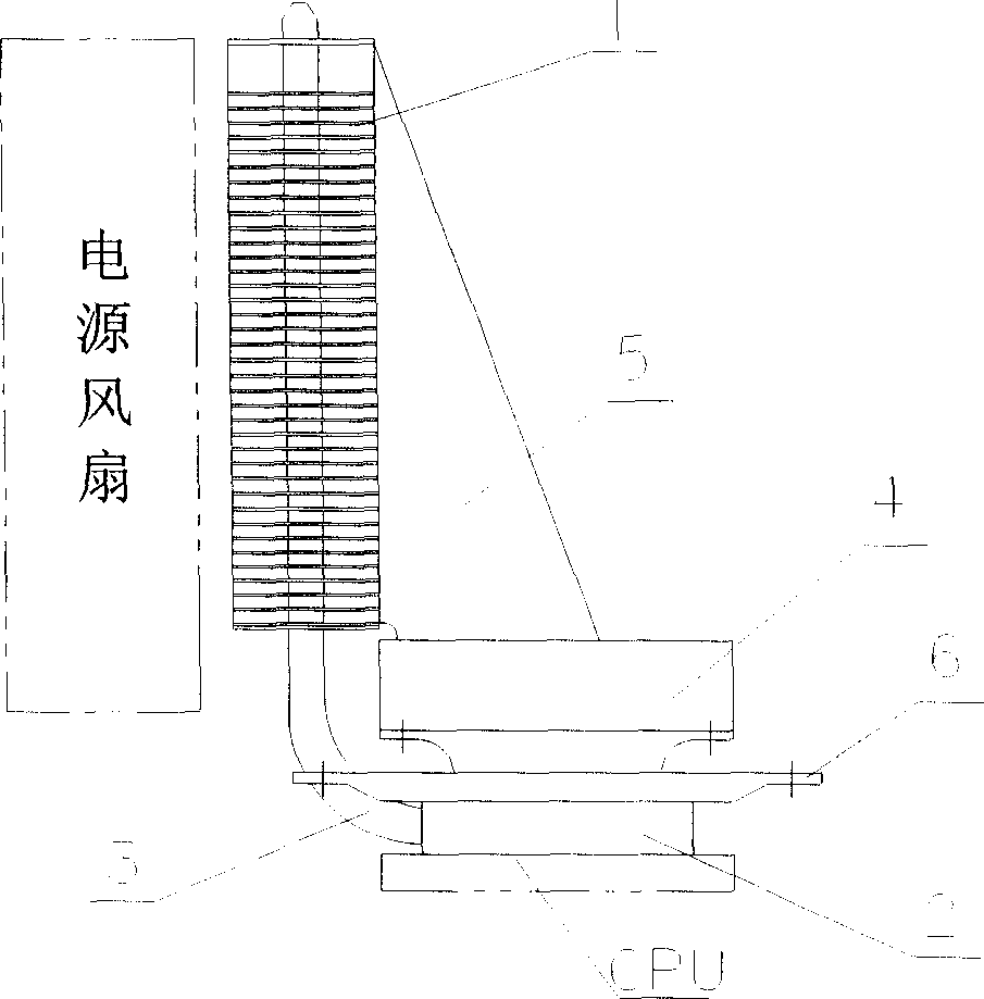
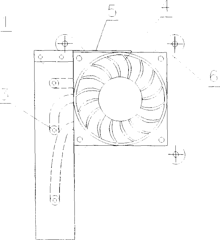
[0013] see figure 1 and figure 2 , the present invention includes a cooling fin 1, a contact plate 2 made of a copper plate that is in contact with the CPU for heat transfer, and three heat pipes 3 connected to the contact plate 2. The other end of the heat pipe 3 is interspersed in a row of cooling fins 1 parallel to the contact plate 2 and at a certain distance, and the cooling fins 1 are close to the power supply fan. A low-speed fan 4 is supported by a support 6 above the contact plate 2 , and a corner plate 5 is provided between the cooling fin 1 and the side of the support 6 for supporting and fixing.

[0014] When the present invention is installed, the screws around the bracket 6 are connected to the CPU radiator backboard on the mainboard back, so that the bottom plane of the touch panel 2 is close to the upper surface of the CPU.

[0015] After starting up, the heat generated by the CPU is quickly transferred to each heat pipe 3 through the touch panel 2 . After ...


PUM


Abstract

A CPU radiator for computer mainframe relates to computer technology field. It contains radiation fin and touch panel for conducting heat by contacting CPU. Structural feature is said touch panel being copper plate with heat tube s, each heat tube another end interpenetration in a row of radiation fins which are abutted against to power supply fan. Compared with current technology, the present invention has low noises, fast heat radiation, and noise without undulation along with systems operation program and environmental temperature variation.

Description

technical field [0001] The invention relates to the technical field of computers, in particular to a CPU radiator used in a main chassis. Background technique [0002] With the rapid increase of computer CPU main frequency, its power and calorific value are getting bigger and bigger. In order to meet the heat dissipation design specifications of the CPU, the traditional CPU radiator blows the heat generated by the CPU away from the heat sink through the fan installed on the heat sink, and then the heat in the chassis is discharged from the chassis by the power supply fan or system fan. In order to achieve the purpose of quickly cooling the CPU and components on the motherboard, the fan speed should be increased to 4000RPM-5000RPM, or even higher. The increase in fan speed will produce unbearable high-decibel noise and chassis vibration. After adopting the wind speed control technology on the motherboard, although the speed and noise of the fan can be appropriately reduced,...

Claims


Application Information

Patent Timeline
Patent Type & Authority Applications(China)
IPC IPC(8): G06F1/20H01L23/46
Inventor 关明慧
Owner TSINGHUA TONGFANG CO LTD
Why Eureka
Try Eureka