Joy stick controller

A technology of controllers and joysticks, which is applied in the direction of mechanical control devices, manual control mechanisms, control mechanisms, etc., can solve the problems of not being able to obtain the operating feeling of the joystick, the reduction of the quietness of the joystick, and the increase of the load force, and achieve improved Operational stability, improved quietness, and easy and quick installation

Inactive Publication Date: 2007-01-10
MITSUMI ELECTRIC CO LTD
View PDF1 Cites 7 Cited by
  • Summary
  • Abstract
  • Description
  • Claims
  • Application Information

AI Technical Summary

Problems solved by technology

[0004] According to the above-mentioned prior art, the spring returns to the neutral position by releasing the operating force of the operating lever 5. Especially when the operating lever 5 moves in a direction inclined relative to the X direction or the Y direction, the load force of the two springs 9 and 10 increases. , so there is a problem that a certain joystick operation feeling cannot be obtained
In addition, when the joystick is operated, since the spring expands and contracts with the movement of the cranks 3 and 4, there is a peculiar mechanical squeaking sound unique to the spring, which has the disadvantage of reducing the quietness during the joystick operation.

Method used


Image

  • Joy stick controller
  • Joy stick controller
  • Joy stick controller

Examples


Embodiment

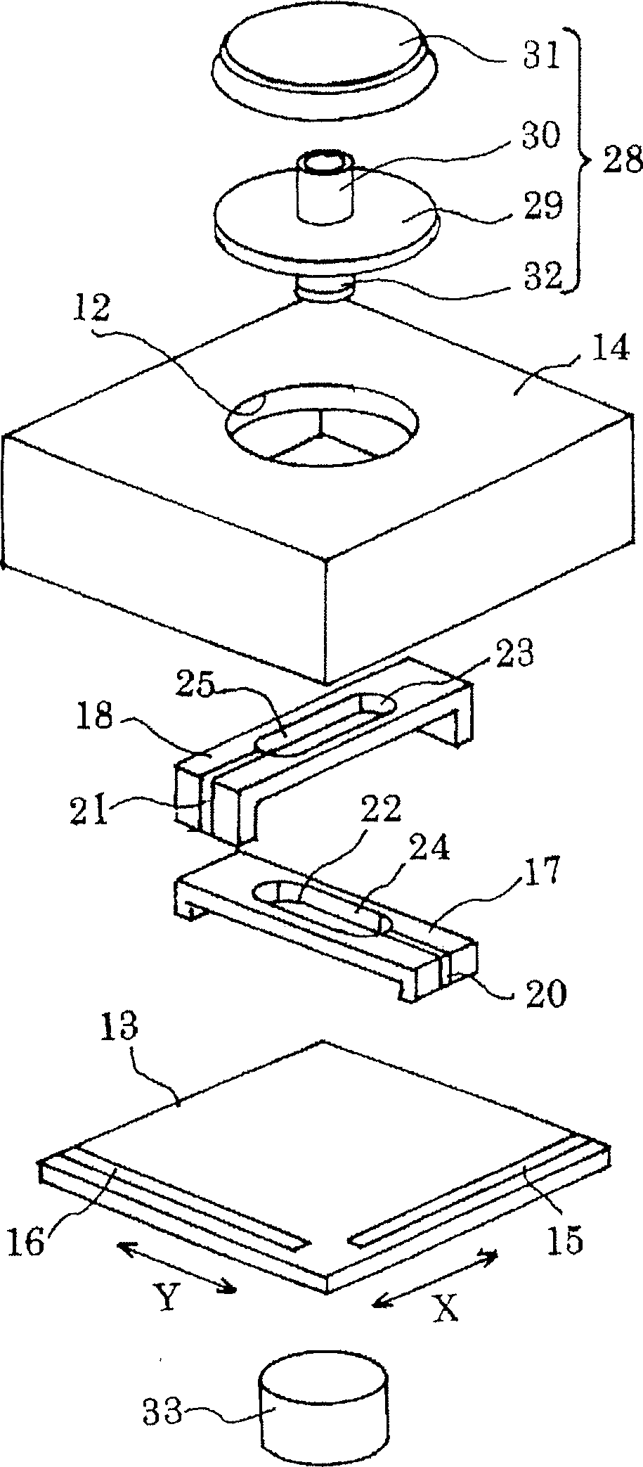
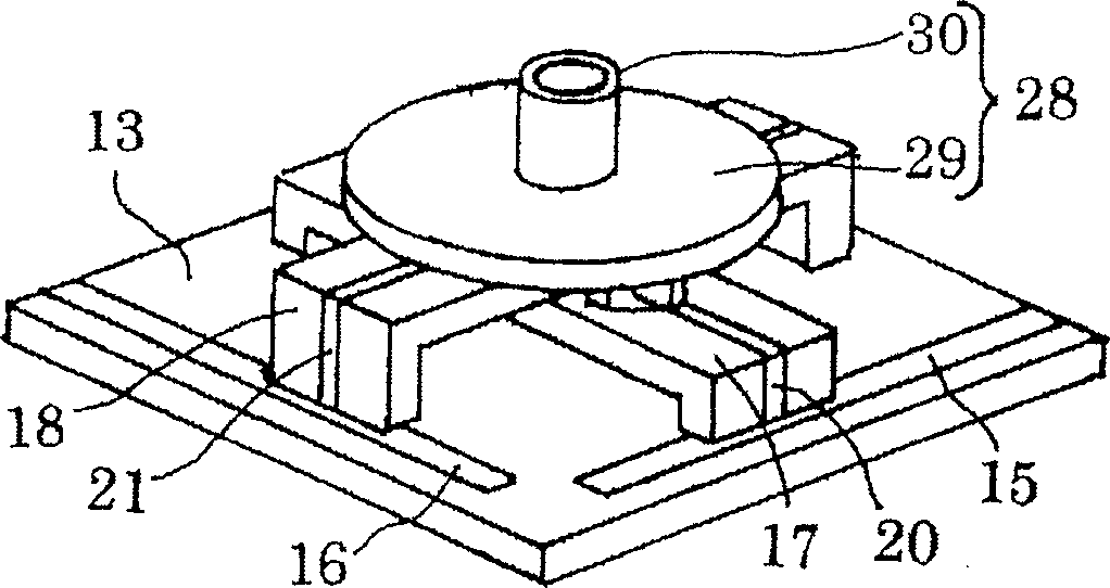
[0041] Below, according to Figure 1 to Figure 4 An example of the present invention will be described. In addition, in the present embodiment, the operating rod 28 is provided to freely move and operate from the XY coordinate origin (neutral) position to an arbitrary position. Operation is not limited to this setting.

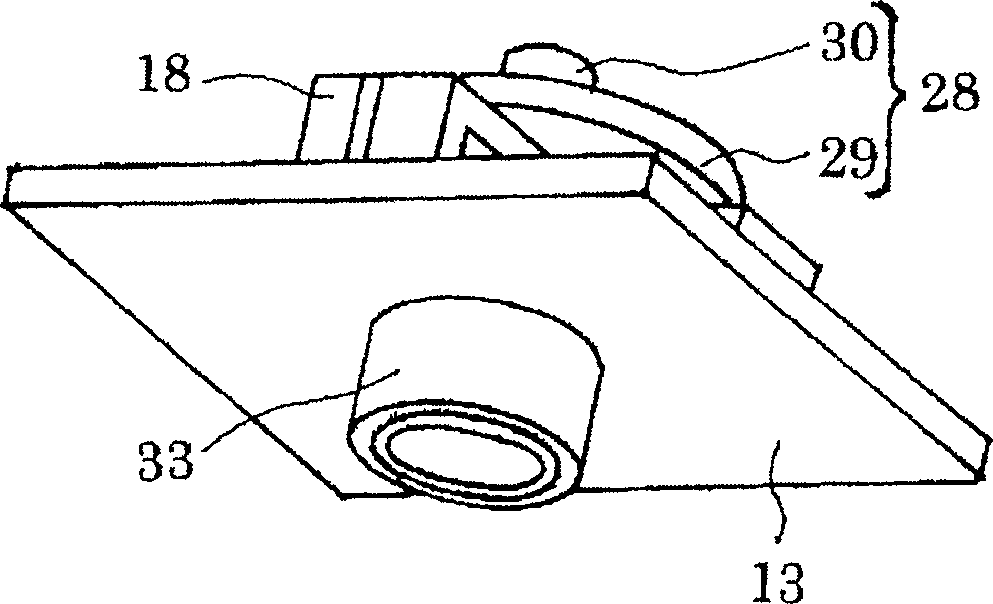
[0042] In this embodiment, both the neutral return magnet part 33 on the lower side of the substrate 13 and the lower end of the joystick shaft on the upper side of the substrate 13 are formed with permanent magnets, so that the N pole or S pole of the magnet part is aligned with the shaft part 30. There is a magnetic force that attracts each other between the S poles or N poles. Therefore, by attracting the shaft portion 30 with the magnet member 33 , the operation lever 28 is returned to neutral. In addition, if the shaft lower end is made of a material attracted and moved by the magnet member 33, it is not limited to a permanent magnet (including a rubbe...


PUM


Abstract

The invention provides a joy stick device capable of improving silence while obtaining fixed stick operating feeling. The device is provided with cranks 17 and 18 provided on a substrate 13 freely movably in X and Y directions, and an operating stick 28 having a shaft part 30 penetrating through the center parts of the both cranks 17 and 18, and a lower end part of the shaft part 30 is formed of a magnet 32. A magnet 33 being a magnet member for position return is fixed onto the bottom surface of the substrate 13 corresponding to the neutral position in the X and Y directions. After a stick operation, the magnet 32 at the shaft side is moved right above the magnet 33 by magnetic force to thereby make the operating stick 28 automatically immediately return to the midpoint position.

Description

technical field [0001] The present invention relates to a joystick controller device, and more particularly to a joystick controller device of a planar operation type that returns to its original position by magnetic force after a movement input operation. Background technique [0002] Conventionally, joystick controller devices used on game machines and the like, such as Figure 10 and Figure 11 As shown, on the base plate 2 covered by the box cover 1, the crank 3 and the crank 4 that intersect perpendicularly to each other can be freely moved in the X direction and the Y direction, respectively, and at the same time, there is a freely movable installation operation on the above-mentioned box cover 1. Structure of the lever (operating member) 5 . The operating lever 5 is composed of a shaft portion 6 whose lower end portion is fitted to the central portion of the cranks 3, 4, a circular collar portion 7 provided at the middle portion of the shaft portion 6, and a knob por...

Claims


Application Information

Patent Timeline
Patent Type & Authority Applications(China)
IPC IPC(8): H01H25/04G06F3/0338
CPCG05G9/047G05G2009/04766G05G2009/04714G05G5/05
Inventor 石丸博史
Owner MITSUMI ELECTRIC CO LTD
Why Eureka
Try Eureka