Light conductive plate and back light module

A technology of backlight module and light guide plate, applied in optics, nonlinear optics, instruments, etc., can solve the problems of unsuitable mold design simplification requirements, small microstructure size, etc., to eliminate light beam phenomenon, design simplification, and simple structure Effect

Inactive Publication Date: 2007-01-24
HONG FU JIN PRECISION IND (SHENZHEN) CO LTD +1
View PDF0 Cites 13 Cited by
  • Summary
  • Abstract
  • Description
  • Claims
  • Application Information

AI Technical Summary

Problems solved by technology

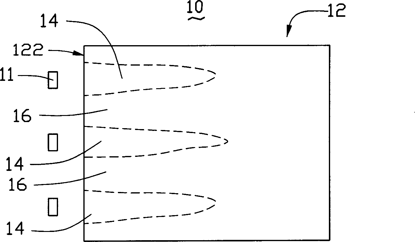
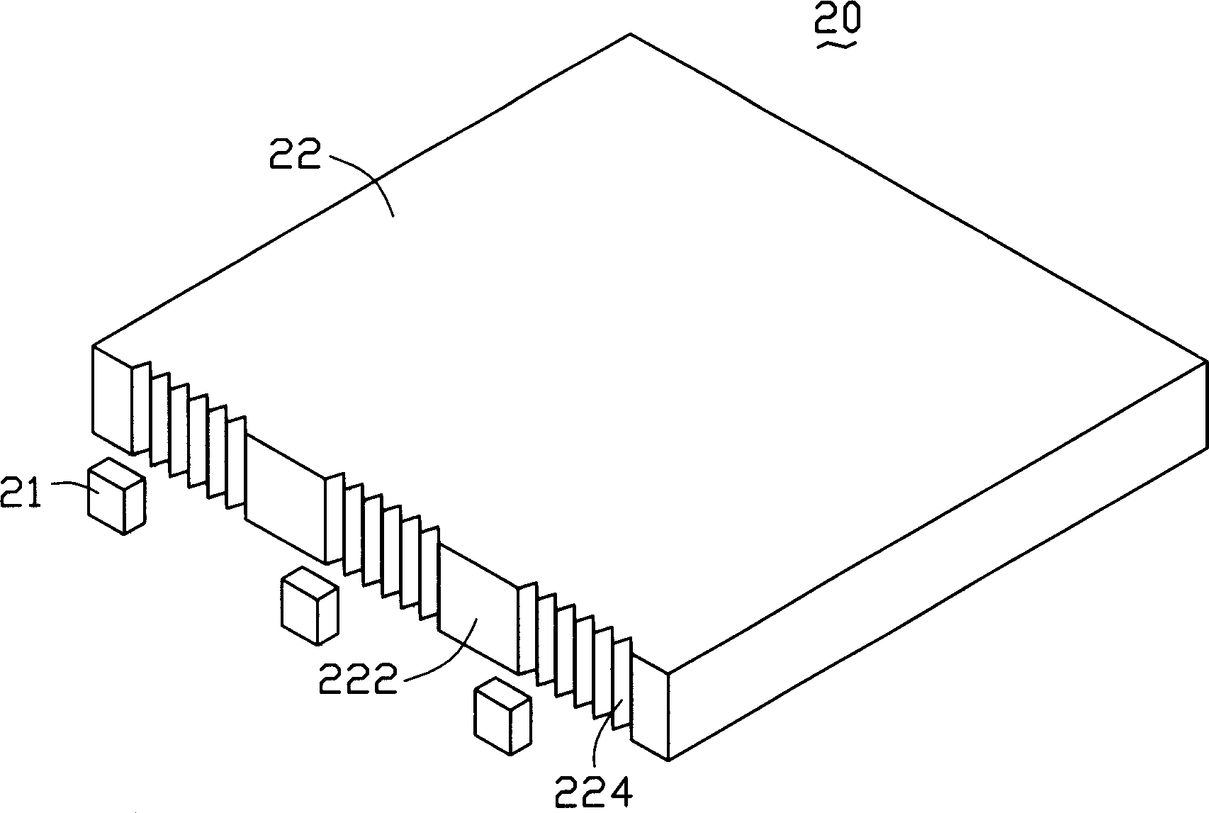
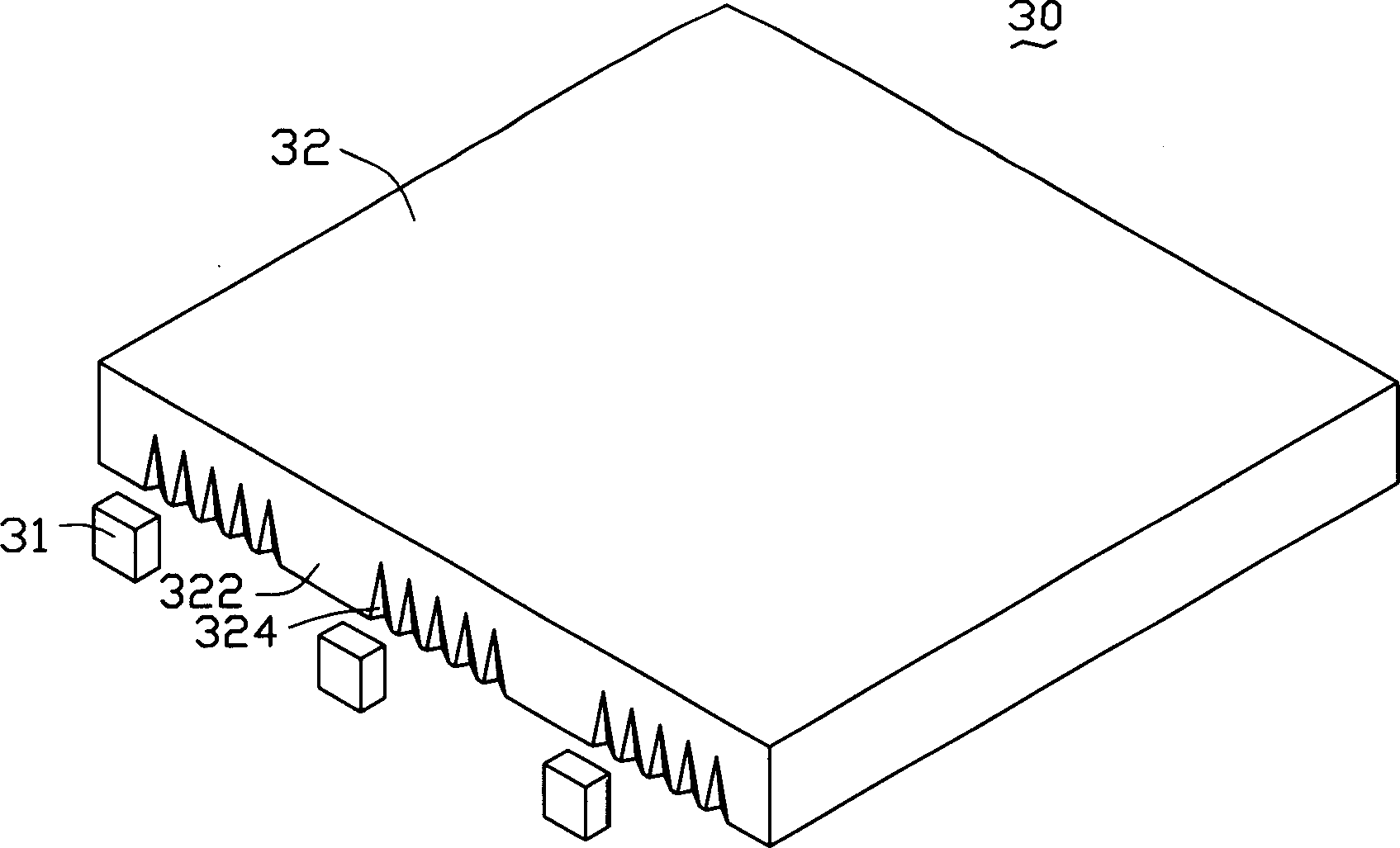
[0009] The light-incident surface microstructures of the backlight modules 20 and 30 (serrated prism structure 224 or tapered groove structure 324) can eliminate the beam phenomenon to a certain extent, but the groove pitch of the above-mentioned microstructures is about hundreds of microns, The small size of the microstructure is not suitable for the simplified requirements of mold design

Method used


Image

  • Light conductive plate and back light module
  • Light conductive plate and back light module
  • Light conductive plate and back light module

Examples


Embodiment Construction

[0025] The embodiments of the present invention will be further described in detail below in conjunction with the accompanying drawings.

[0026] See Figure 4 , the first embodiment of the present invention provides a backlight module 40 , which includes a plurality of LED point light sources 41 , a light guide plate 42 and a plurality of reflectors 43 . The light guide plate 42 includes a light incident surface 422, a light exit surface 425 connected to the light incident surface 422, and a bottom surface 426 opposite to the light exit surface 425. Protrusion 424, the protrusion 424 is a triangular cylinder arranged along the direction perpendicular to the axis of the light incident surface 422, which protrudes outward from the light incident surface 42, and a multi-layer reflective film is formed on the surface of each protrusion 424 (not shown in the figure) Show). Each LED point light source 41 is correspondingly close to each protrusion 424 . Each reflector 43 has a s...


PUM

PropertyMeasurementUnit
lengthaaaaaaaaaa
reflectanceaaaaaaaaaa
transmittivityaaaaaaaaaa

Abstract

The light guiding plate includes following parts: an incident lightface of containing at least one bulge or groove; a light coming out face connected to the incident lightface; back plane opposite to the light coming out face; multiple layers of reflecting film formed on surface of the bulge or groove. Using the light guiding plate, a backlight module disclosed in the invention includes at least one spot light source and at least reflex housing cooperated with the light guiding plate. Each spot light source is corresponding to bulge or groove on incident lightface of the light guiding plate. Being near to and enclosing the spot light source, the reflex housing is in use for reflecting and returning part of light back to enter to the light guiding plate again. The disclosed backlight module eliminates phenomena of light columns on incident lightface so as to raise evenness of emergence light.

Description

【Technical field】 [0001] The invention relates to a light guide plate and a backlight module using the light guide plate, in particular to an edge-light backlight module. 【Background technique】 [0002] Due to the advantages of lightness, thinness, and low power consumption, liquid crystal displays are widely used in modern information equipment such as notebook computers, mobile phones, and personal digital assistants. Because the liquid crystal itself in the liquid crystal display does not have light-emitting characteristics, in order to achieve the display effect, it is necessary to provide a surface light source device for the liquid crystal display panel, such as a backlight module, whose function is to provide a surface light source with sufficient brightness and uniform distribution to the liquid crystal display panel. The backlight module can be divided into two types according to the structure: the side-light backlight module and the direct-light backlight module. ...

Claims


Application Information

Patent Timeline
Patent Type & Authority Applications(China)
IPC IPC(8): G02F1/1335
Inventor 张仁淙
Owner HONG FU JIN PRECISION IND (SHENZHEN) CO LTD
Why Eureka
Try Eureka